Wireless communication device

a wireless communication and wireless technology, applied in the direction of power management, near-field systems using receivers, instruments, etc., can solve the problems of no efficient method other than charging, users' troublesome charging, and limit such improvement, so as to facilitate the charging of the battery provided in the wireless communication device, suppress the excess power consumption, and avoid the effect of halting the wireless communication device system

Active Publication Date: 2008-03-06
SEMICON ENERGY LAB CO LTD
View PDF28 Cites 123 Cited by
  • Summary
  • Abstract
  • Description
  • Claims
  • Application Information

AI Technical Summary

Benefits of technology

[0019]In the present invention, a wireless communication device is provided with a battery capable of being charged by wireless, so that the charge of the battery provided in the wireless communication device can be facilitated, and a wireless communication device permanently capable of transmitting and receiving information to and from outside without replacement of batteries can be obtai

Problems solved by technology

However, there is a limit to such improvement to deal with the prolonged operating time.
Further, for charging batteries which are built into cellular phones, portable televisions, and the like, there is no efficient methods other than charging from a household alternating current power supply through an AC adaptor or from a commercially available primary battery.
Therefore, charging has been troublesome for users, and it has been necessary for users to bring with an AC adaptor or a primary battery itself when such electric devices are used outdoors for a long time.
However, there has been a prob

Method used


Image

  • Wireless communication device
  • Wireless communication device
  • Wireless communication device

Examples


embodiment mode 1

[0045]In this embodiment mode, an example of a wireless communication device including a power receiving device portion will be described with reference to drawings.

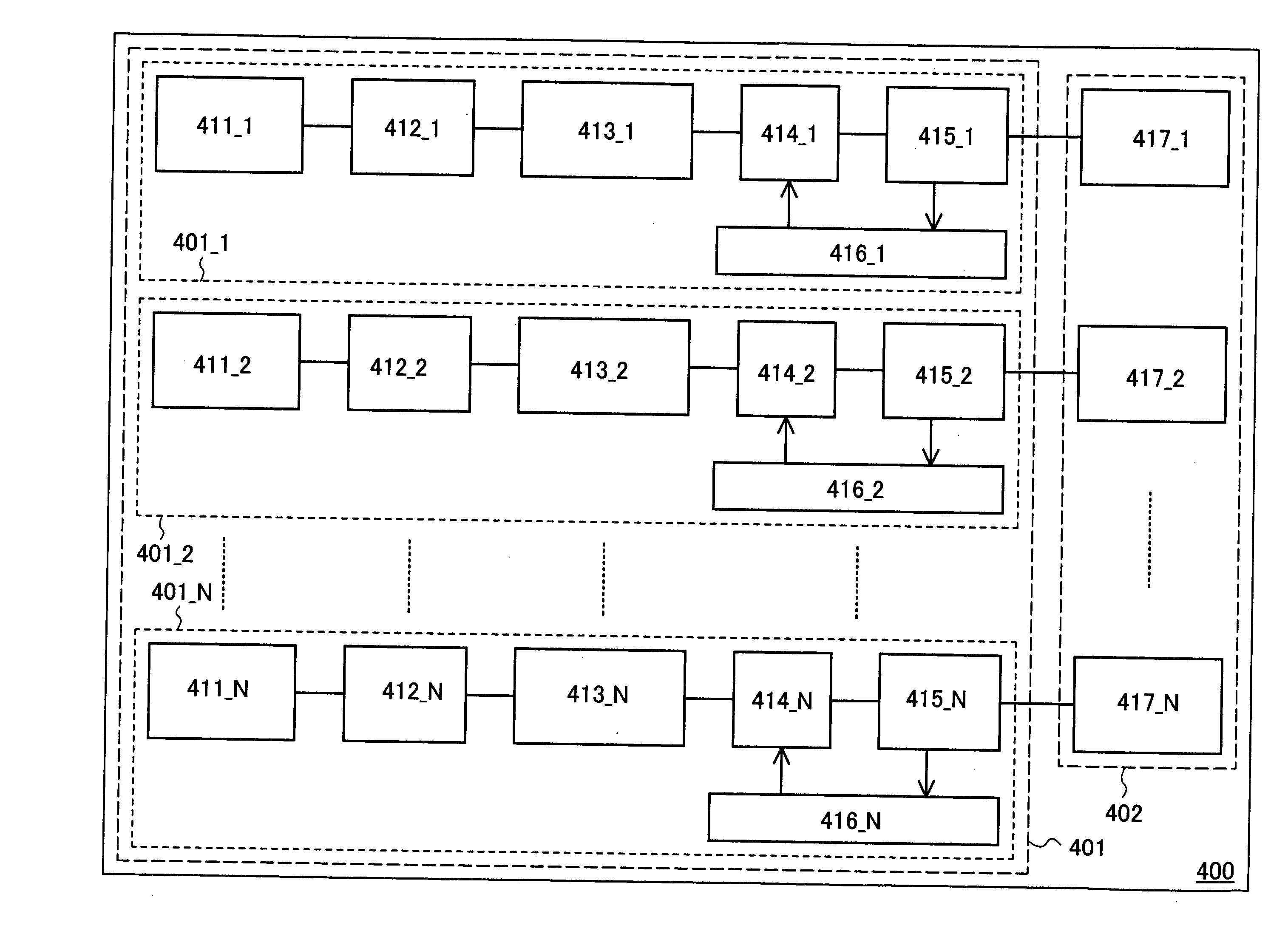
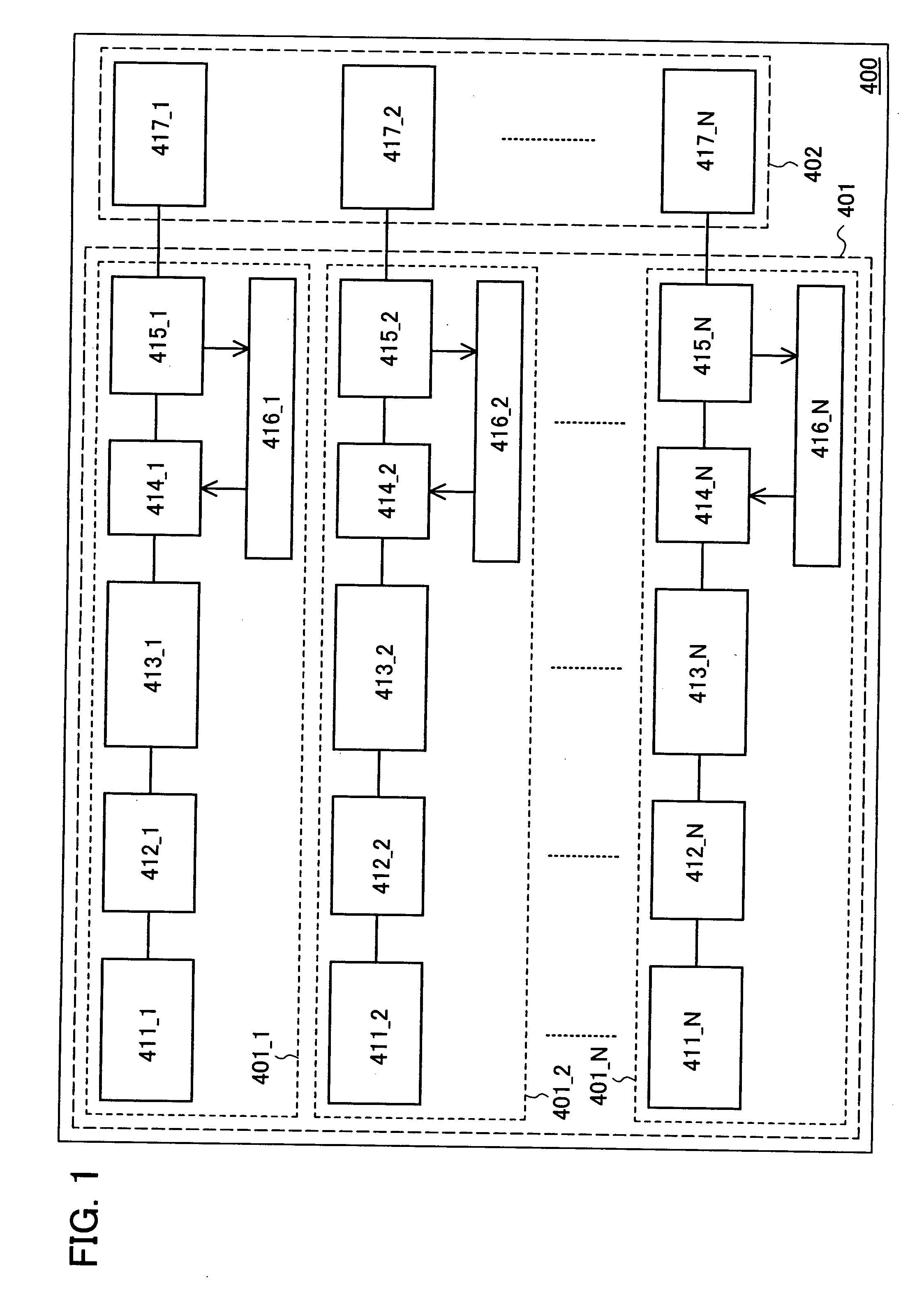
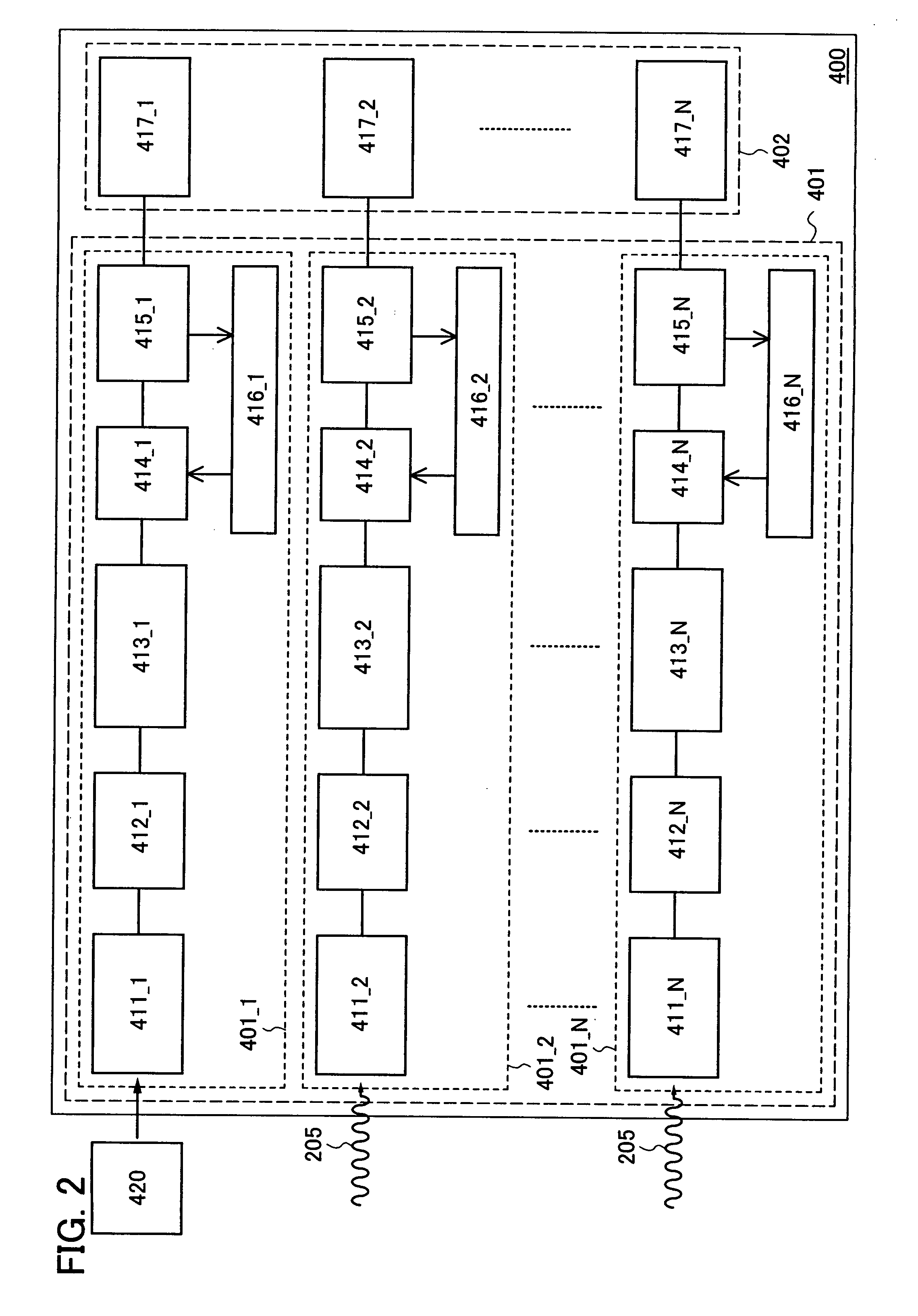
[0046]A wireless communication device 400 described in this embodiment mode has a power receiving device portion 401 and a power supply load portion 402 (see FIG. 1).

[0047]The power receiving device portion 401 has a plurality of RF battery portions each including an antenna circuit, a rectifier circuit, a voltage control circuit, a switch, a charge control circuit, and a battery. FIG. 1 illustrates a structure in which the power receiving device portion 401 is provided with N(N≦3 in FIG. 1) RF battery portions. A first RF battery portion 401_1 includes a first antenna circuit 411_1, a first rectifier circuit 412_1, a first voltage control circuit 413_1, a first switch 414_1, a first charge control circuit 416_1, and a first battery 415_1.

[0048]Similarly, a second RF battery portion 401_2 includes a second antenna circui...

embodiment mode 2

[0078]In this embodiment mode, a structure of a wireless communication device (for example, a cellular phone, a digital video camera, or the like) having a display means will be described as an example of the wireless communication device described in the above embodiment mode with reference to drawings.

[0079]The wireless communication device 400 described in this embodiment mode has the power receiving device portion 401 including the first RF battery portion 401_1 and the second RF battery portion 401_2, and the power supply load portion 402 including a display portion 430 provided with a pixel portion 431 and a display control portion 432 and including an integrated circuit portion 433 (see FIG. 6). The integrated circuit portion 433 is a circuit that processes signals other than those in the display portion 430. The display portion 430 is provided with the pixel portion 431 and the display control portion 432 for controlling the pixel portion 431. Note that kinds of a display el...

embodiment mode 3

[0096]In this embodiment mode, an example of a wireless communication device, which is different from that in the above embodiment modes, will be described with reference to drawings. Specifically, as an example of the wireless communication device, an RFID (Radio Frequency Identification) tag (also referred to as an IC (Integrated Circuit) tag, an IC chip, an RF tag, a wireless tag, a wireless chip, or an electronic tag) is given for the description.

[0097]The wireless communication device (hereinafter also described as an “RFID tag”) described in this embodiment mode will be described with reference to block diagrams illustrated in FIGS. 9 and 10.

[0098]An RFID tag 100 illustrated in FIG. 9 has a first antenna circuit 101, a second antenna circuit 121, a signal processing circuit 110, a first battery 105, and a second battery 125. The signal processing circuit 110 has circuits for controlling charge and discharge of the first battery, circuits for controlling charge and discharge of...


PUM


Abstract

It is an object of the present invention to facilitate charge of a battery of a wireless communication device. In addition, it is another object of the present invention to provide a wireless communication device capable of transmitting and receiving individual information without battery replacement which is required due to the power consumption of a battery. A wireless communication device includes a plurality of antenna circuits and a plurality of batteries electrically connected to any one of the plurality of antenna circuits through a switch, where the plurality of batteries are each electrically connected to a different circuit, the plurality of antenna circuits receive electric waves so that the plurality of batteries electrically connected to the plurality of antenna circuits are charged, and at least one of the plurality of antenna circuits receives an electric wave having a different frequency.

Description

BACKGROUND OF THE INVENTION[0001]1. Field of the Invention[0002]The present invention relates to a wireless communication device. In particular, the present invention relates to a wireless communication device that transmits and receives data and receives electric power through an electric wave.[0003]2. Description of the Related Art[0004]In recent years, various electric appliances have become widely used and wide varieties of appliances have appeared on the market. In particular, the spread of portable wireless communication devices has been remarkable. As an example, cellular phones, portable televisions, and the like have become very convenient, which is contributed by the improvement in definition of display portions and durability of batteries and by the reduction of power consumption of the wireless communication devices. The portable wireless communication device has a structure in which a rechargeable battery is built-in to secure electric power. As a battery, a secondary b...

Claims


Application Information

Patent Timeline
IPC IPC(8): H04B1/38H04M1/00H04W52/00G06K19/07H02J7/00H02J50/00H02J50/10H02J50/20H02J50/40H04B1/59H04B5/02
CPCG06K19/0702G06K19/0723G06K19/0707B42D25/00B42D25/305
Inventor SATO, TAKEHISAOSADA, TAKESHI
Owner SEMICON ENERGY LAB CO LTD
Why Eureka
Try Eureka