Injection Valve for Fuel Injection

a technology of injection valve and fuel injection, which is applied in the direction of valve operating means/release devices, machines/engines, magnetic bodies, etc., can solve the problems of limited manufacturing steps, and achieve the effects of less assembly steps, less complicated and cost-effective manufacturing, and simple injection molding methods

Inactive Publication Date: 2008-03-13
ROBERT BOSCH GMBH
View PDF40 Cites 26 Cited by
  • Summary
  • Abstract
  • Description
  • Claims
  • Application Information

AI Technical Summary

Benefits of technology

[0003] An injection valve according to the present invention provides the advantage of a less complicated and more cost-effective manufacture since the injection valve is made up of considerably fewer components than the conventional injection valves; in addition, these components are able to be produced by simple injection molding methods. The reduced number of components requires fewer assembly steps and thus less assembly time and is more cost-effective with respect to automatic assembly machines and jointing machines. The manufacturing steps are limited to placing the magnetic core fitted with the magnetic coil in an extrusion die, die casting the magnetic yoke element from magnetic material, subsequent injection-molding of the magnetic yoke element with solenoid coil and iron core to produce the plastic housing, and inserting valve member with valve-closure spring and valve-seat support having the spray-orifice disk in the prefabricated plastic housing. The production steps for the injection molding may be carried out with the aid of a so-called cube system, which uses a block-shaped extrusion die having vertical junction planes, which is rotated by 90° following each production step in order to implement the next production step. At 0°, the cylindrical magnetic core supporting the magnetic coil is inserted; at 90°, the extrusion coating of magnetic coil and magnetic core with the magnetic material takes place in which a gapless connection to the magnetic core is produced. At 180°, the plastic-extrusion coating to produce the plastic housing is carried out, and at 270°, the finished plastic housing with the valve-seat support as well as the connection piece and connection lug for the solenoid coil formed thereon is removed.

Problems solved by technology

The manufacturing steps are limited to placing the magnetic core fitted with the magnetic coil in an extrusion die, die casting the magnetic yoke element from magnetic material, subsequent injection-molding of the magnetic yoke element with solenoid coil and iron core to produce the plastic housing, and inserting valve member with valve-closure spring and valve-seat support having the spray-orifice disk in the prefabricated plastic housing.

Method used


Image

  • Injection Valve for Fuel Injection
  • Injection Valve for Fuel Injection
  • Injection Valve for Fuel Injection

Examples


Embodiment Construction

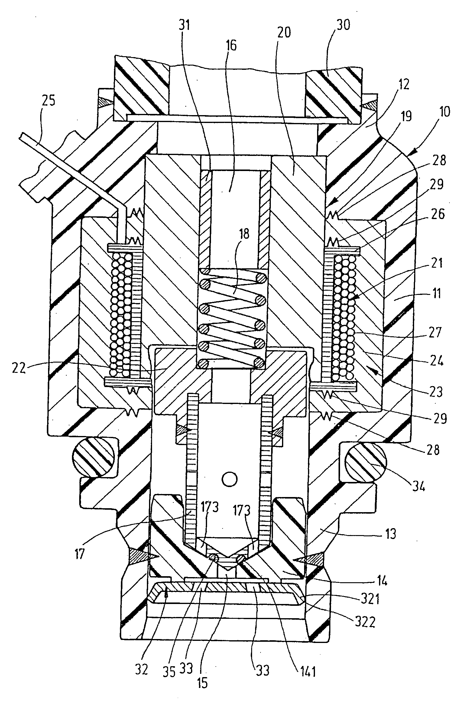
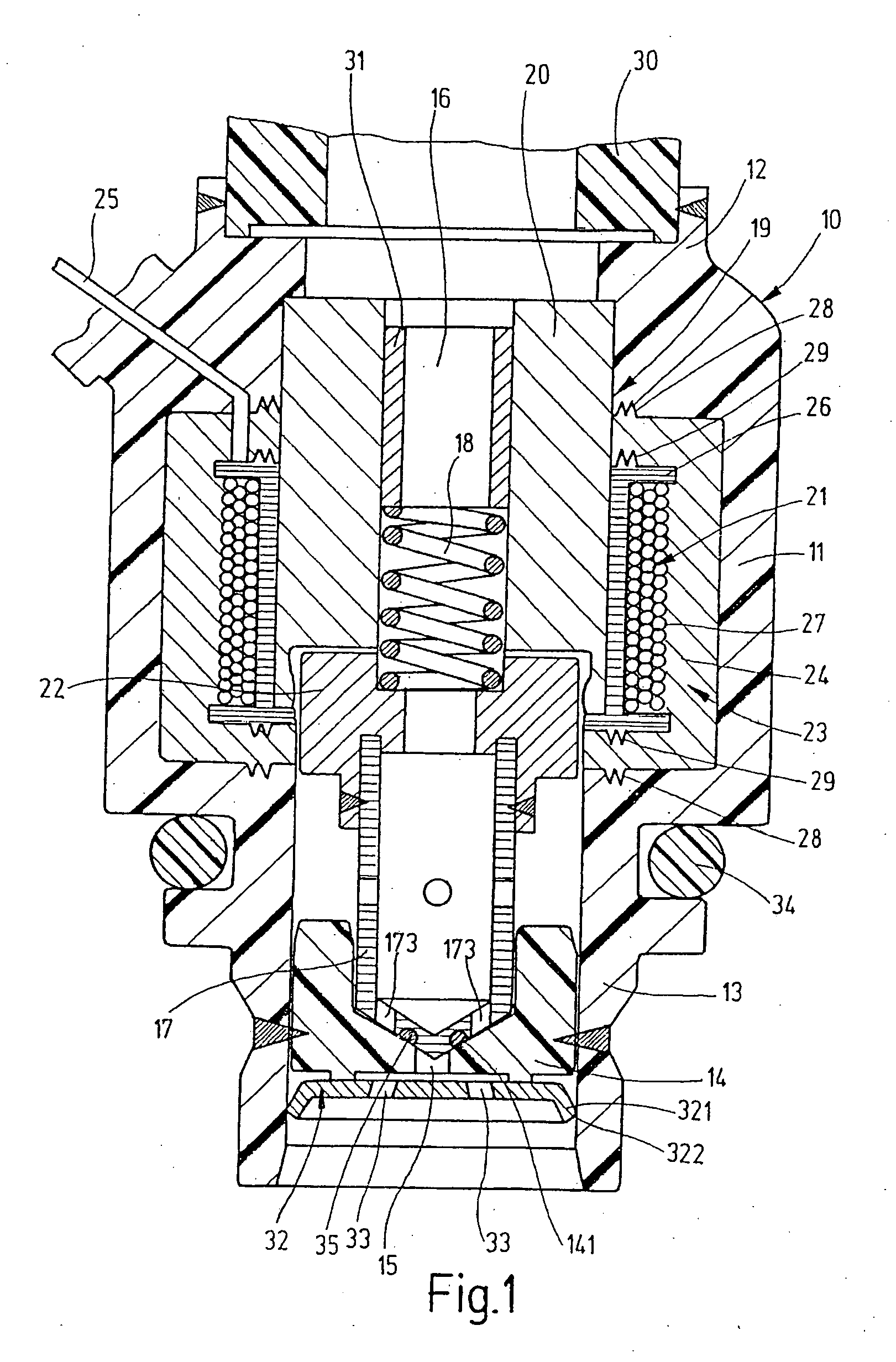
[0014] The injection valve for fuel-injection systems, e.g., of motor vehicles, shown in longitudinal section in FIG. 1, has a plastic housing 10, made of a fuel-tight plastic, at whose one end a connection piece 12 is formed and at whose other end a valve-seat support 13 is formed. Connection piece 12 and valve-seat support 13 are combined into one piece by plastic coat 11 lying between them, in order to form complete plastic housing 10. Connection piece 12 is used to connect the injection valve to a fuel-supply line 30, a so-called rail. Valve-seat support 13 accommodates a valve-seat body 14 in which a valve opening 15 is located, which is surrounded by a valve seat 141. Valve opening 15 is connected to connection piece 12 via a fuel-flow path 16 provided in the interior of plastic housing 11. A valve member 17, which cooperates with a valve seat 141 formed on valve-seat body 14, is used to control valve opening 15 for the purpose of spray-discharging fuel via valve opening 15. A...


PUM


Abstract

A fuel injection valve has a connection piece for a fuel-supply line, a valve-seat support having a valve-seat body provided with a valve opening, a solenoid for activating a valve member, which controls the valve opening, and a plastic extrusion coat enclosing the connection piece, the solenoid and the valve-seat support. To achieve a cost-effective manufacture by requiring fewer components for the injection valve and providing a reduction in the assembly costs, the connection piece and the valve-seat support are made of plastic and designed as one-piece plastic housing together with the plastic extrusion coat. The yoke element for closing the magnetic circuit of the solenoid, which extends across the magnetic core and magnetic armature, is a magnetic material extrusion coat, which encloses the solenoid coil and adjoins the magnetic core in a gapless manner and ends in front of the magnetic armature with a gap clearance.

Description

FIELD OF THE INVENTION [0001] The present invention relates to an injection valve for fuel injection, in particular for internal combustion engines of motor vehicles. BACKGROUND INFORMATION [0002] In an injection valve for fuel-injection systems of internal combustion engines, e.g., as described in German patent document DE 195 03 224, the connection piece is machine-cut from a steel pipe and accommodates the plastic coil brace of the electromagnet wound with the excitation winding and simultaneously forms the magnetic core of the electromagnet. The valve-seat support, which is likewise made from a steel pipe, is joined to the bottom side of the coil brace; it partially encloses the magnetic armature connected to the plastic valve needle, the magnetic armature being guided in the valve-seat support so as to be displaceable by sliding and partially projecting into the coil brace. The magnetic yoke between the magnetic core or connection piece and the magnetic armature is formed by a ...

Claims


Application Information

Patent Timeline
Patent Type & Authority Applications(United States)
IPC IPC(8): F02M51/06F16K31/06F02M51/00F02M61/16F02M61/18
CPCF02M51/005F02M51/0685F02M61/166Y10S239/04F02M61/1853H01F7/1607Y10S239/19F02M61/168
Inventor BAYER, JOHANN
Owner ROBERT BOSCH GMBH
Why Eureka
Try Eureka