
Reflecting packed column

a technology of packed columns and columns, applied in the direction of dispersed particle separation, chemical/physical/physicochemical processes, separation processes, etc., can solve the problems of large production area, high equipment investment, difficult to realize, etc., to increase the separation and response efficiency of equipment largely, stable high-speed mass transfer, and high-speed mass transfer

Inactive Publication Date: 2008-03-20
FANG DAHUI
View PDF3 Cites 7 Cited by
  • Summary
  • Abstract
  • Description
  • Claims
  • Application Information

AI Technical Summary

Benefits of technology

[0012] In accordance with this invention, by reflecting the packing materials, most phases can be dispersed in the reflecting packing mass transfer fields, the dispersed multiple phase units strike to each other so that the purpose of refining the units and thus to increase largely the interphase contact specific areas can be realized, and thus the unit surface can be refreshed quickly and the stable high speed mass transfer in the multiple phases are obtained. The further purpose of this invention is to keep the same solute of various substances away from balance in the chemical reactions in the reflecting packing mass transfer field so as to keep the mass transfer in high speed and thus to increase the separation and response efficiency of the equipment largely.
[0031] (2) the diameter of the fluid ball in the reflecting packed column is in the range of 20-50 mm, the height of grade one fluid bed is in the range of 100-250 mm, the liquid phase and the gas phase keep the mass transfer in high speed under the function of the continuous spin and planetary motion of the fluid balls, the spray liquid is utilized completely, so that there is no stringent requirement on the pressure and atomization degree of the spray liquid. Thus, the consumption of the spray liquid is reduced, and the operation cost of the reflecting packed column is decreased;
[0034] (5) the reflecting packed column has a simple structure, is easy to produce and maintain, has parts that are less easy to wear-out, and in which the scaling buildup can be avoided resulting from the planetary motion of the fluid balls;

Problems solved by technology

However, in this way, a huge column body is generally needed for the mass transfer equipment, resulting in a large produce area and high equipment investment.
However, this is difficult to realize due to the technical limit of these equipments themselves.
For example, with the increase of gas flow speed, the resistance force increases sharply for plate column, and the energy consumption increases, the spray liquid drop for spray column increases, the interphase contact specific area decreases, and thus the desired highly efficient mass transfer cannot be realized.
Then, the interphase mass transfer effect cannot be improved further.
However, it is difficult to implement methods and structures for conventional packed columns which would not only strengthen the mass transfer but also consume less energy.
However, although some success has been achieved in increasing the mass transfer efficiency, there is still lack of technology to improve dispersion of the mass transfer phases.
However, this structure is complicated, the adaptive range of the gas flow speed inside of the tower is limited, so that different gas flow rates required by most absorption processes cannot be guaranteed, and the electricity consumption with the addition of venture tube is relatively high.

Method used


Image

  • Reflecting packed column
  • Reflecting packed column
  • Reflecting packed column

Examples


Embodiment Construction

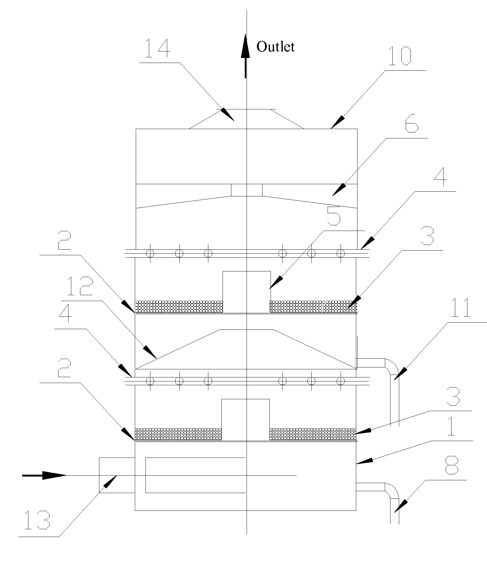
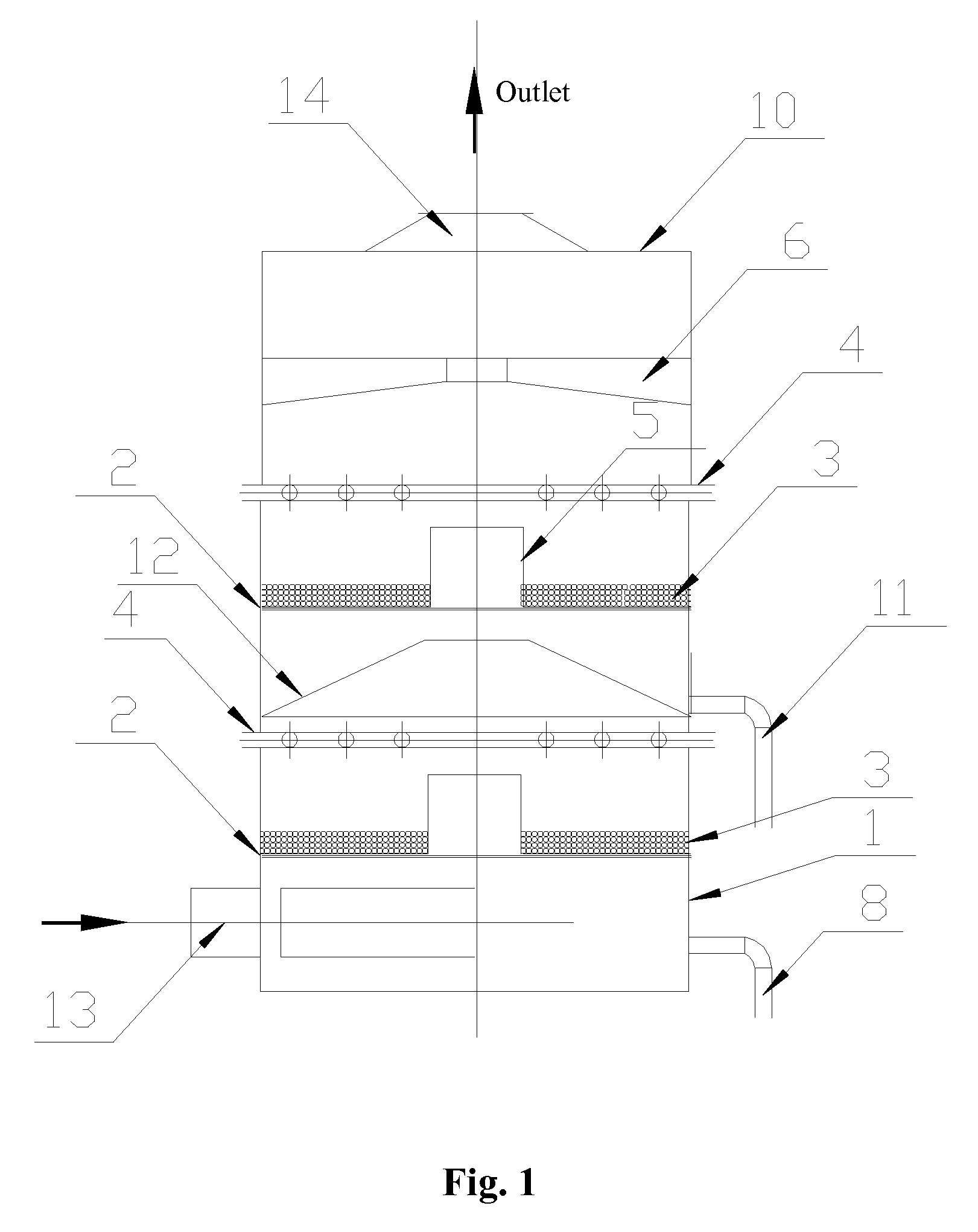
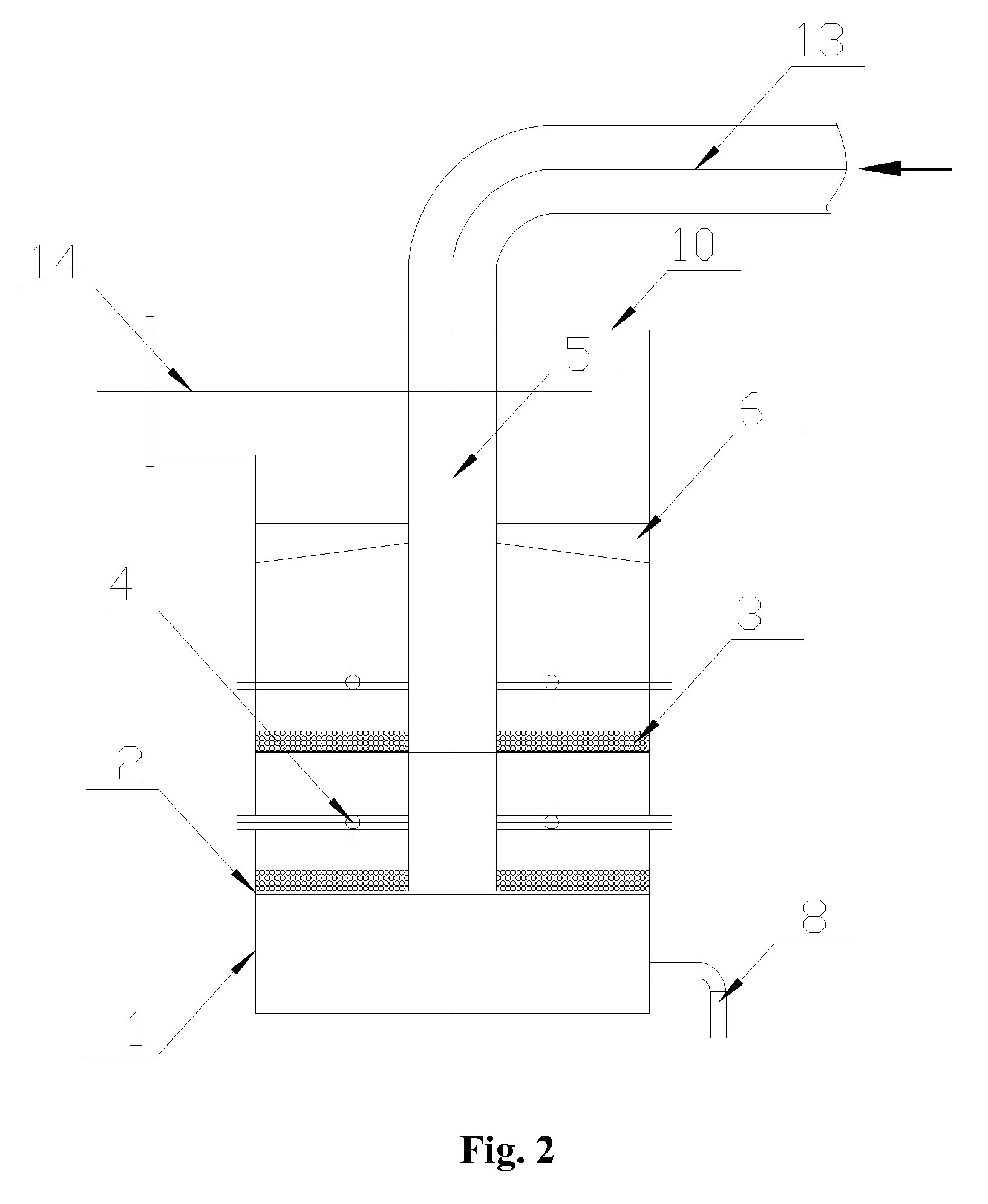
[0047] As shown in FIGS. 1-10, a reflecting packed column comprises an outer cylinder 1, a support plate 2 located inside of the outer cylinder 1, a plurality of fluid balls 3 set on the support plate 2, and an absorption liquid spray tube 4, wherein an inner cylinder 5 is connected to the center of the support plate 2 and a plurality of openings 16 and a plurality of deflectors 15 connected to the openings are disposed on the circular edge of the inner cylinder 5.

[0048] A central through hole for housing the inner cylinder 5 is disposed on the support plate 2. When the external gas flow inlet 13 is disposed at the lower portion of the outer cylinder 1, the inner cylinder 5 is dead-ended, as shown in FIG. 1. A plurality of openings 16 and a plurality of deflectors 15 connected to the openings are also set along the circular edge of the central through hole of the support plate 2. The deflector 15 and the support plate 2 cross. Optimally, the inclination angle of the deflector 15 is...


PUM

PropertyMeasurementUnit
heightaaaaaaaaaa
heightaaaaaaaaaa
inclination angleaaaaaaaaaa

Abstract

This invention teaches a packed column, comprising an outer cylinder, a support plate, and a plurality of fluid balls, wherein an inner cylinder is connected to the center of the support plate, and a plurality of openings and deflectors connected to the openings are disposed on the circular edge of the inner cylinder. By setting a circular spin and planetary travel path for the fluid balls, a series of problems influencing the mass transfer speed are solved. This invention has the following characteristics: 1) the technical problems such that the gas and liquid contact area of static bed packing is small and the operation of turbulent bed is unstable are solved completely; 2) the spray liquid is utilized completely, the consumption of the spray liquid is reduced and the operation cost of the reflecting packed column is decreased; and there is no stringent requirement on the pressure and atomization degree to the spray liquid; 3) the mass transfer effect having a low resistance and high efficiency can be achieved without increasing the air pressure; 4) an absorption liquid circulation system with dual or more loops can be realized; the purpose of multilevel flow split and multistage liquid processing can be reached; and 5) the reflecting packed column has a simple structure and has fewer easily worn-out parts; the scaling buildup can be avoided resulting from the planetary motion of the fluid balls. The reflecting packed column of this invention is applicable to various mass transfer processes.

Description

CROSS-REFERENCE TO RELATED APPLICATIONS [0001] This application is a continuation of International Patent Application No. PCT / CN2006 / 000915 with an international filing date of May 8, 2006, designating the United States, now pending, and further claims priority benefits to Chinese Patent Application No. 200510031623.6, filed on May 28, 2005. The contents of the aforementioned specifications are incorporated herein by referenceBACKGROUND OF THE INVENTION [0002] 1. Field of the Invention [0003] This invention relates to a mass transfer equipment capable of purifying gases and removing solid dust, being used for various mass transfer processes, and more particularly to a reflecting packed column. [0004] 2. Description of the Related Art [0005] Protecting environment and saving energy are important endeavors for various countries in the world so as to sustain economic growth. In order to reduce product and investment cost, relevant enterprises are in an urgent need of highly efficient, ...

Claims


Application Information

Patent Timeline
Patent Type & Authority Applications(United States)
IPC IPC(8): B01D47/00
CPCB01D53/18B01D53/78B01J2219/30207B01J2208/00884B01J19/0053
Inventor FANG, DAHUI
Owner FANG DAHUI
Learn More