Magnet arrangement for a planar magnetron background and summary of the invention

a planar magnetron and background technology, applied in the field of arrangement of magnets, can solve the problems of irregular wear of targets, cycloid electron trajectories, planar magnetrons, etc., and achieve the effect of improving the sputter effect, reducing the heating of the substrate, and increasing the probability of ionizing the sputter gas atom through collision with electrons

Inactive Publication Date: 2008-03-20
DEPPISCH THOMAS +1
View PDF1 Cites 7 Cited by
  • Summary
  • Abstract
  • Description
  • Claims
  • Application Information

AI Technical Summary

Benefits of technology

[0006] To improve the sputter effect, magnets are utilized near the target. Their magnetic field keeps the plasma at the target. Through the interaction of the magnetic and the electric fields the charge carriers in the plasma primarily no longer move parallel to the electric field but also at right angles to it, which results in cycloid electron trajectories. As the deflection radii of the electrons are much smaller than those of the ions, due to their low mass, the electrons concentrate before the target surface. Therefore, the probability that sputter gas atoms are ionized via collisions with electrons is much higher. As a result of the E×B drift of the electrons—the electrons follow a trajectory referred to as racetrack—and the concentration of plasma before the target surface, the electrons no longer fly directly to the substrate. Heating of the substrate is therefore reduced.
[0007] The much heavier ions fall onto the target, which has the effect of a negative electrode or cathode and sputter this. Ionizations therefore largely occur where the magnetic field vector is parallel to the target surface. The plasma is most dense here, as a result of which the target is most strongly eroded at this point. The glow discharge plasma is virtually enclosed by the magnetic field and the electron trajectories are extended by the fact that the electrons rotate around the magnetic field lines serving as axes, thereby increasing the rate at which gas atoms and electrons collide.
[0023] If the invention is advantageously designed, even long, wide targets with only a single racetrack or erosion track can be coated. As the two poles of the magnet arrangement interlock slightly in the middle, it is possible to achieve a high target utilization and a virtually complete re-coating free target surface with only one linear movement. In so doing, north and south pole are arranged relatively to each other so that meander-like racetracks are achieved on the target. Two opposing meanders are so close to one another that the target surface is evenly sputtered when executing a linear movement toward the target length. The height of lift is ± half a meander interval.

Problems solved by technology

Through the interaction of the magnetic and the electric fields the charge carriers in the plasma primarily no longer move parallel to the electric field but also at right angles to it, which results in cycloid electron trajectories.
A disadvantage which both cylinder magnetrons, which are occasionally also referred to as pipe cathodes, and planar magnetrons feature is the irregular wear of the targets.
This causes electron congestion in this area, which results in a denser ionization and subsequently in increased erosion of the target.
As a result, a re-coating between the individual meander loops can occur and the target—which is larger than the substrate—cannot be fully sputtered.

Method used


Image

  • Magnet arrangement for a planar magnetron background and summary of the invention
  • Magnet arrangement for a planar magnetron background and summary of the invention
  • Magnet arrangement for a planar magnetron background and summary of the invention

Examples


Embodiment Construction

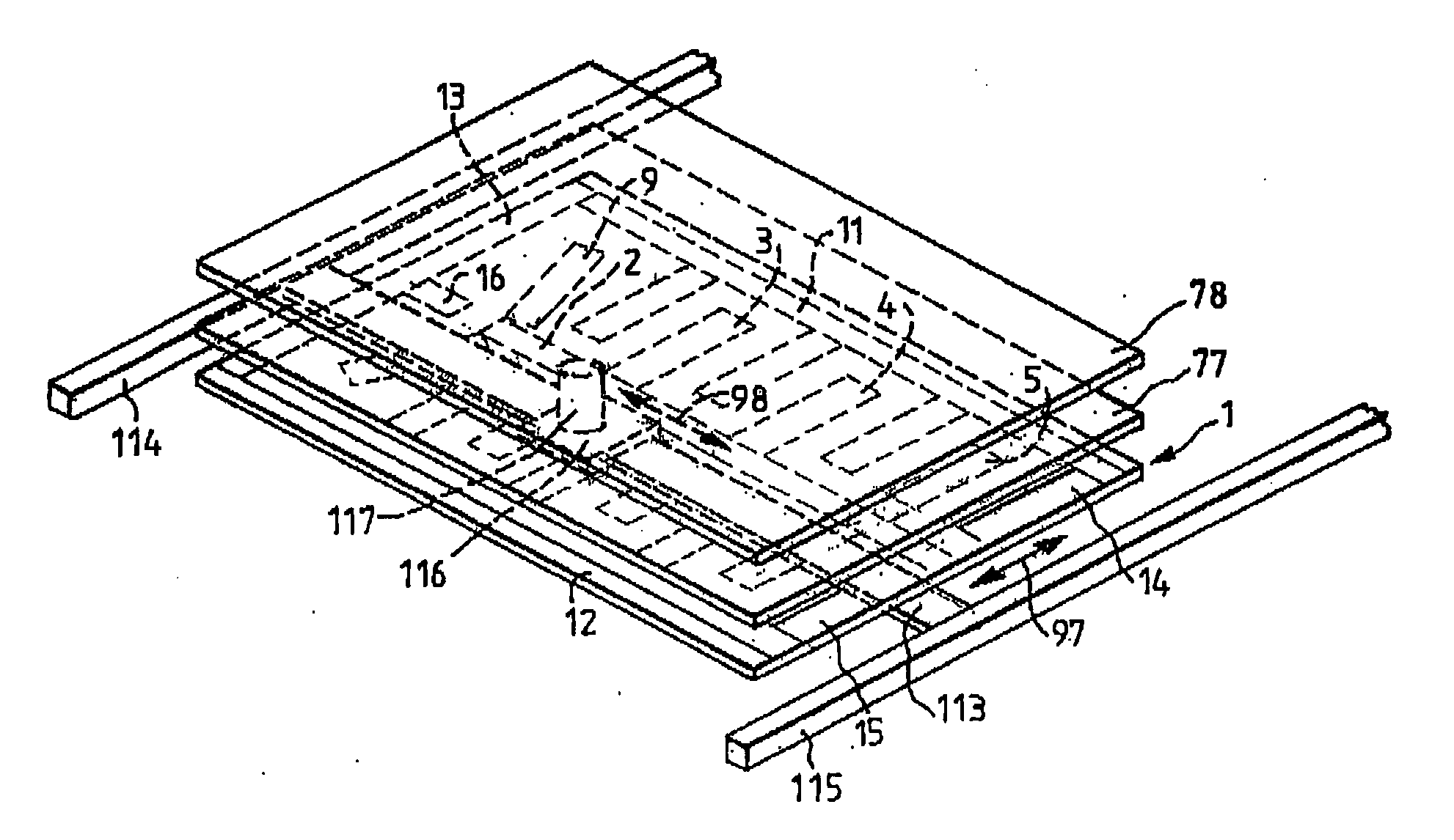
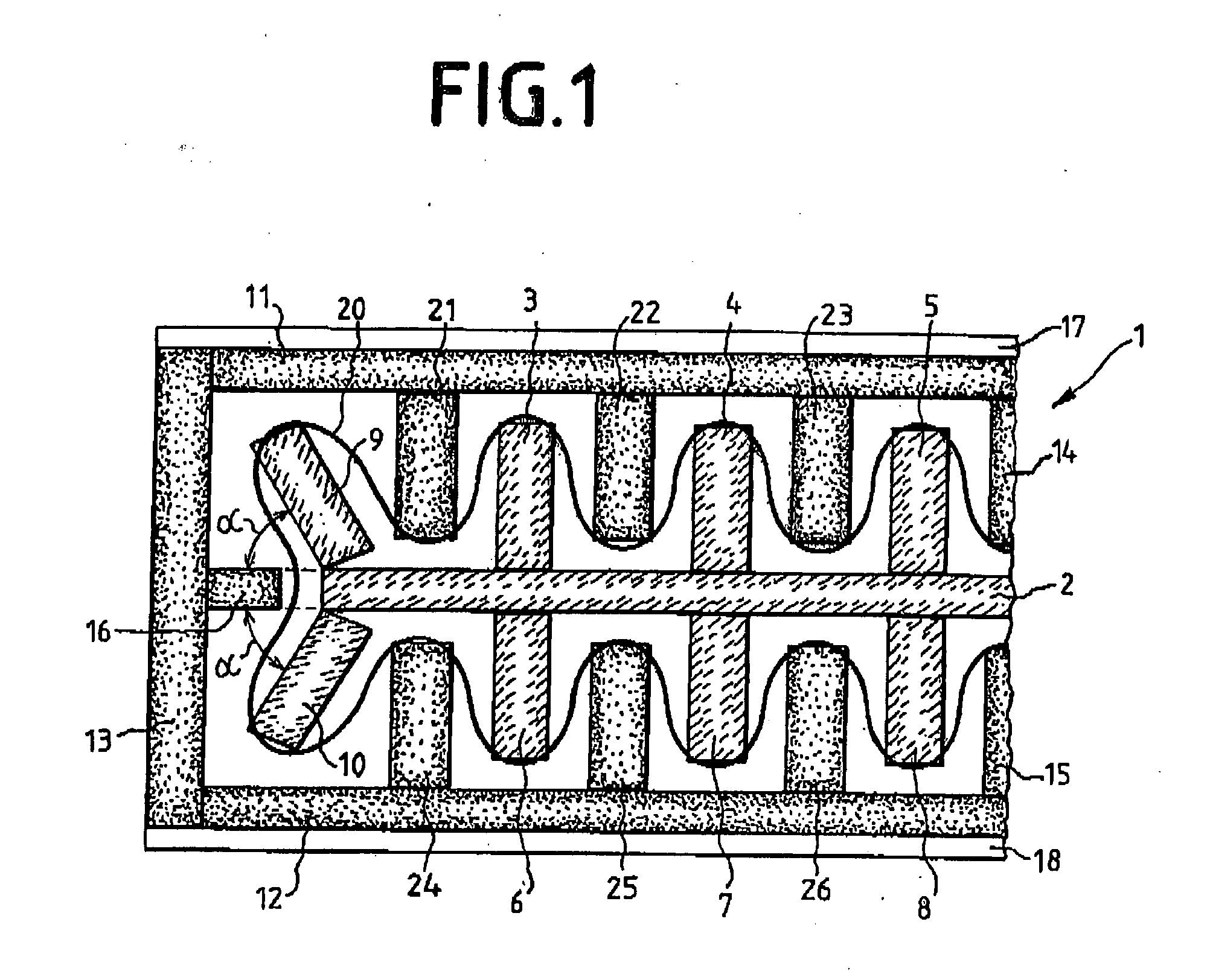
[0029]FIG. 1 shows a partial representation of an initial magnet configuration 1 in accordance with the invention, with which constant utilization of a target is enabled. In so doing, movements in two different directions are, however, required. On the one hand, the magnet system must be moved along the length of the target and, on the other, an additional movement along the target width is required, so that no re-coating is obtained. The magnet configuration 1 shown in FIG. 1 continues on the right side (not shown) in a reversed image. The magnetic south pole of the magnet configuration consists of a transverse bar 2, on which arms 3 to 8 are arranged parallel to each other and perpendicular to bar 2.

[0030] On the one end of bar 2, two additional arms 9, 10 of the magnetic south are provided for, the longitudinal axis of which is arranged at an angle α to the longitudinal axis of the perpendicular bar 2. The angle α is approx. 60°. At the end of the right and not displayed side of...


PUM

PropertyMeasurementUnit
angles of inclinationaaaaaaaaaa
magnetic arrangementaaaaaaaaaa
magneticaaaaaaaaaa

Abstract

A magnetic arrangement for a planar magnetron, in which an initial magnetic pole encompasses a second magnetic pole. This magnetic arrangement is moved linear in longitudinal direction to a target by a specific value and then moved back in opposite direction by the same value. In one version, an additional perpendicular motion is effected. The magnet arrangement is designed so that north and south pole interlock and waviform racetracks are generated. This enables constant sputtering from the entire target surface.

Description

BACKGROUND AND SUMMARY OF THE INVENTION [0001] This application claims priority under 35 U.S.C. § 119 from European Patent Application No. 050 07 339 filed Apr. 5, 2005, incorporated herein by reference in its entirety. [0002] The invention relates to an arrangement of magnets. [0003] In a sputter system, plasma is generated in a sputter chamber under vacuum. The plasma is understood to be a quasi-neutral many-particle system in the form of gaseous blends of free electrons and ions as well as possible neutral particles, i.e. atoms, molecules or radicals. Positive ions of the plasma are attracted by the negative potential of a cathode, which features a so-called target. The positive ions impinge upon this target and knock away small particles that subsequently precipitate on a substrate. The knocking away of these particles is referred to as “sputtering.” The plasma contains ionized gases, which can, for example, be inert gases such as argon, in the event of a non-reactive sputtering...

Claims


Application Information

Patent Timeline
Patent Type & Authority Applications(United States)
IPC IPC(8): C25D17/00C25F7/00
CPCH01J37/3408H01F7/081C23C14/35
Inventor DEPPISCH, THOMASLOPP, ANDREAS
Owner DEPPISCH THOMAS
Why Eureka
Try Eureka