
Computer-readable recording medium recording a mask data generation program, mask data generation method, mask fabrication method, exposure method, and device manufacturing method

Active Publication Date: 2008-03-20
CANON KK
View PDF10 Cites 5 Cited by
  • Summary
  • Abstract
  • Description
  • Claims
  • Application Information

AI Technical Summary

Benefits of technology

[0013]The present invention provides a computer-readable recording medium recording a mask data generation program and mask data generation method which can shorten the time taken to generate mask data used in multiple exposure.
[0016]According to the present invention, it is possible to shorten the time taken to generate mask data used in multiple exposure.

Problems solved by technology

Unfortunately, the techniques described in Japanese Patent Laid-Open Nos. 2004-221594 and 2005-183981 require the calculation of a TCC and eigenfunction to derive an interference map.
This often complicates the whole numerical calculation to result in a long mask data generation time.
Likewise, this often results in a long mask data generation time.

Method used


Image

  • Computer-readable recording medium recording a mask data generation program, mask data generation method, mask fabrication method, exposure method, and device manufacturing method
  • Computer-readable recording medium recording a mask data generation program, mask data generation method, mask fabrication method, exposure method, and device manufacturing method
  • Computer-readable recording medium recording a mask data generation program, mask data generation method, mask fabrication method, exposure method, and device manufacturing method

Examples


first working example

[0105]Pattern data division using a coherent map 42 will be exemplified. The NA of an exposure apparatus 100 (see FIG. 23) is 0.73, and the wavelength λ of exposure light is 248 nm. Consider a case wherein pattern data 41 (layout pattern) shown in FIG. 11 is a processing target. The pattern data 41 shown in FIG. 11 includes patterns of three contact holes MP201 to MP203. The patterns of the three contact holes MP201 to MP203 have a size of 120 nm.

[0106]The contact hole MP202 is spaced apart from the contact hole MP201 by −310 nm in the y direction. The contact hole MP203 is spaced apart from the contact hole MP202 by 310 nm in the x direction and by −160 nm in the y direction.

[0107]Consider a case wherein an effective light source is of a quadrupole illumination shown in FIG. 12. A circle which has a radius of 1 and is drawn by a white line shown in FIG. 12 indicates σ=1. White portions indicate light irradiated portions. The distance from σ=0 to the center of each pole is given suc...

second working example

[0122]The normal van Cittert-Zernike theorem does not take the influence of polarization into consideration. In recent years, however, the influence of polarization is becoming non-negligible in exposing a pattern whose k1 factor is small.

[0123]In view of this, the inventors of the present invention propose a method of incorporating the polarization effect into the van Cittert-Zernike theorem. More specifically, a control unit 20 derives the van Cittert-Zernike theorem by applying the NA of a projection optical system to the σ value of an effective light source, and three-dimensionally expressing polarized light to be condensed. That is, the control unit 20 performs Fourier transformation by multiplying a function indicating an effective light source by a factor associated with polarization. Polarization factors include a factor which allows x-polarized light to remain as x-polarized, one which turns x-polarized light into y-polarized light, one which turns x-polarized light into z-...


PUM


Abstract

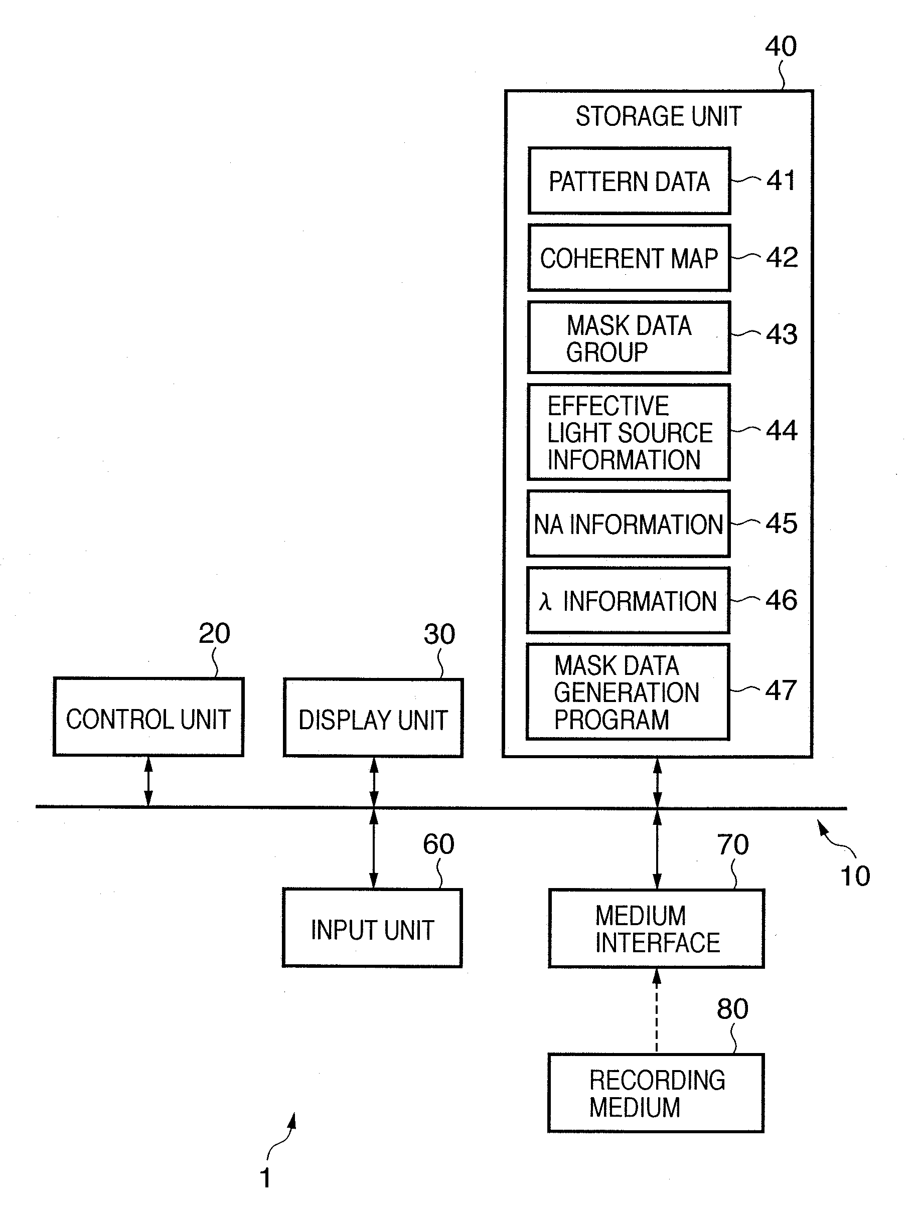
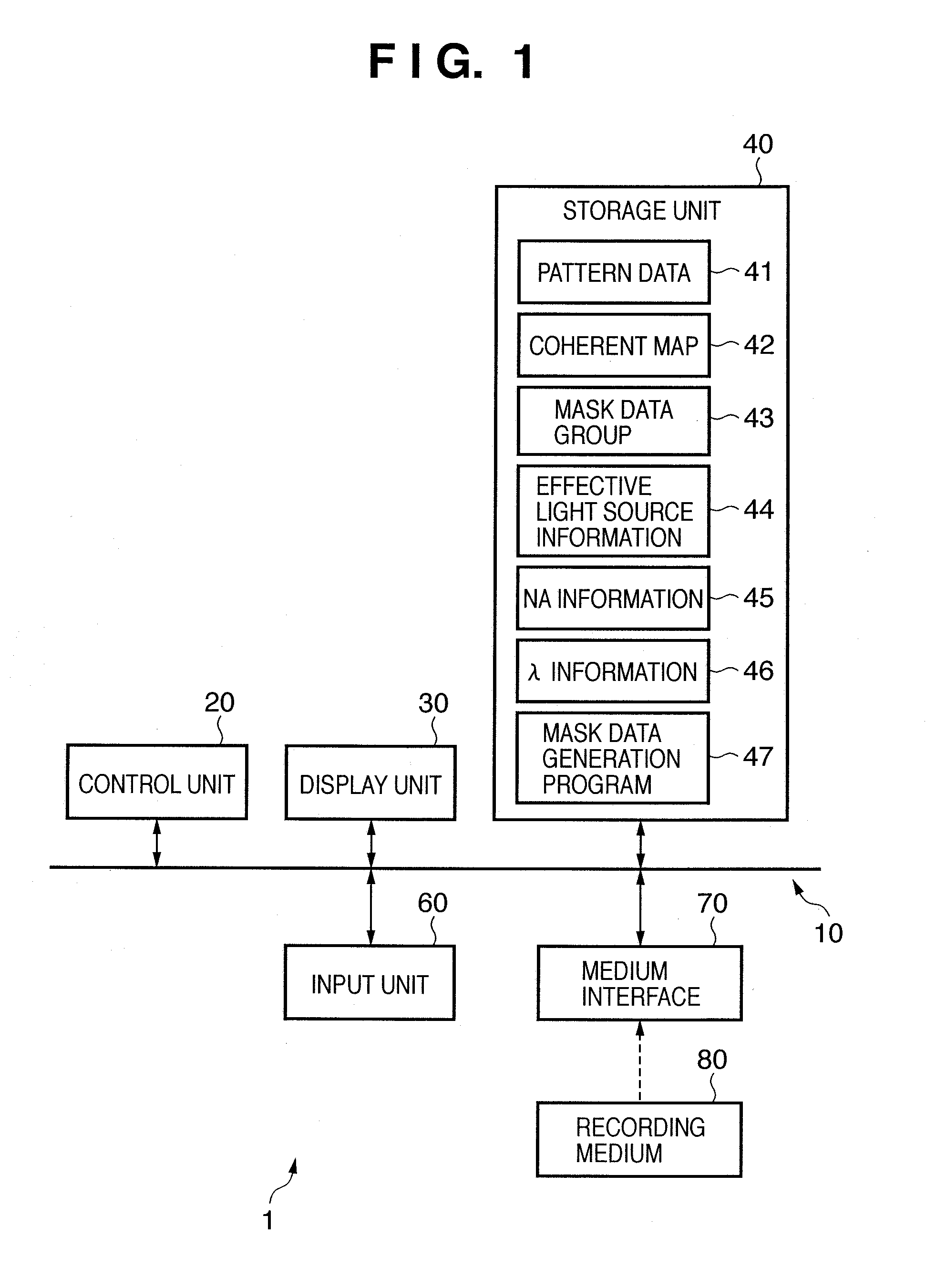
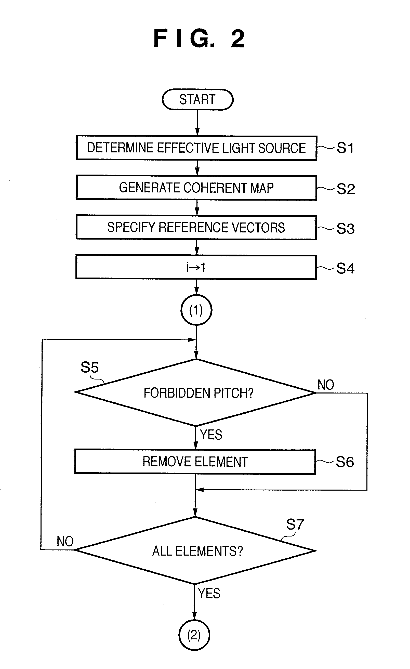
A computer-readable recording medium recording a mask data generation program, the mask data generation program causes the computer to execute: Fourier-Transforming a function indicating an effective light source to generate a coherent map expressing a coherence distribution on the object plane of the projection optical system, on which the mask is arranged; specifying a reference vector from the origin of the coherent map to a region where the coherence is less than a reference value; selecting one element from a pattern including a plurality of elements, and removing, from the pattern, an element existing at a position matching the terminal point of the reference vector arranged such that the center of the selected element serves as the starting point, to generate data of a first pattern different from the pattern; and generating data of a second pattern including the element removed in generating the data of the first pattern.

Description

BACKGROUND OF THE INVENTION[0001]1. Field of the Invention[0002]The present invention relates to computer-readable recording medium recording a mask data generation program, mask data generation method, mask fabrication method, exposure method, and device manufacturing method.[0003]2. Description of the Related Art[0004]There has conventionally been used a projection exposure apparatus which uses a projection optical system to transfer the circuit pattern drawn on a mask (reticle) onto a substrate (e.g. a wafer). Under the circumstances, a demand for a high-resolution exposure apparatus is increasing. Known high-resolution exposure methods increase the numerical aperture (NA) of a projection optical system, shorten the exposure wavelength (λ), or decrease the k1 factor.[0005]Multiple exposure is one of the micropattern exposure technique. Multiple exposure includes a method of superimposing latent image patterns after each of a plurality of exposure processes without executing a dev...

Claims


Application Information

Patent Timeline
IPC IPC(8): G09G5/37G03F1/68
CPCG03F1/144G03F7/70466G03F7/70425G03F1/68
Inventor YAMAZOE, KENJI
Owner CANON KK
Learn More