

Receiver
a communication system and receiver technology, applied in the field of receivers, can solve the problems of power consumption, power consumption, and power consumption of the entire receiver, and achieve the effect of reducing power consumption
- Summary
- Abstract
- Description
- Claims
- Application Information
AI Technical Summary
Benefits of technology
Problems solved by technology
Method used
Image

Examples
first embodiment
[0076]Receiver for the UWB-IR Radio Communication
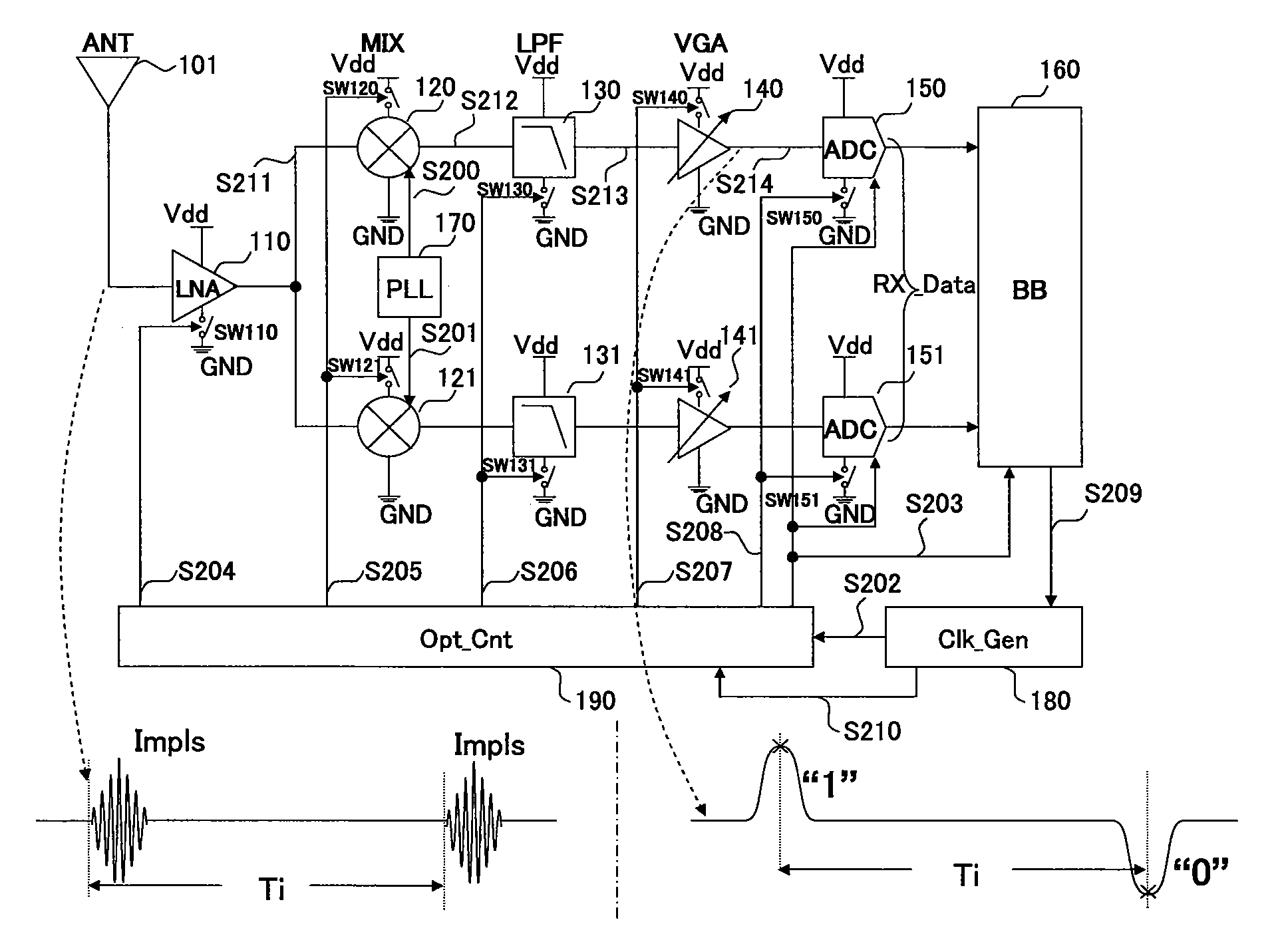
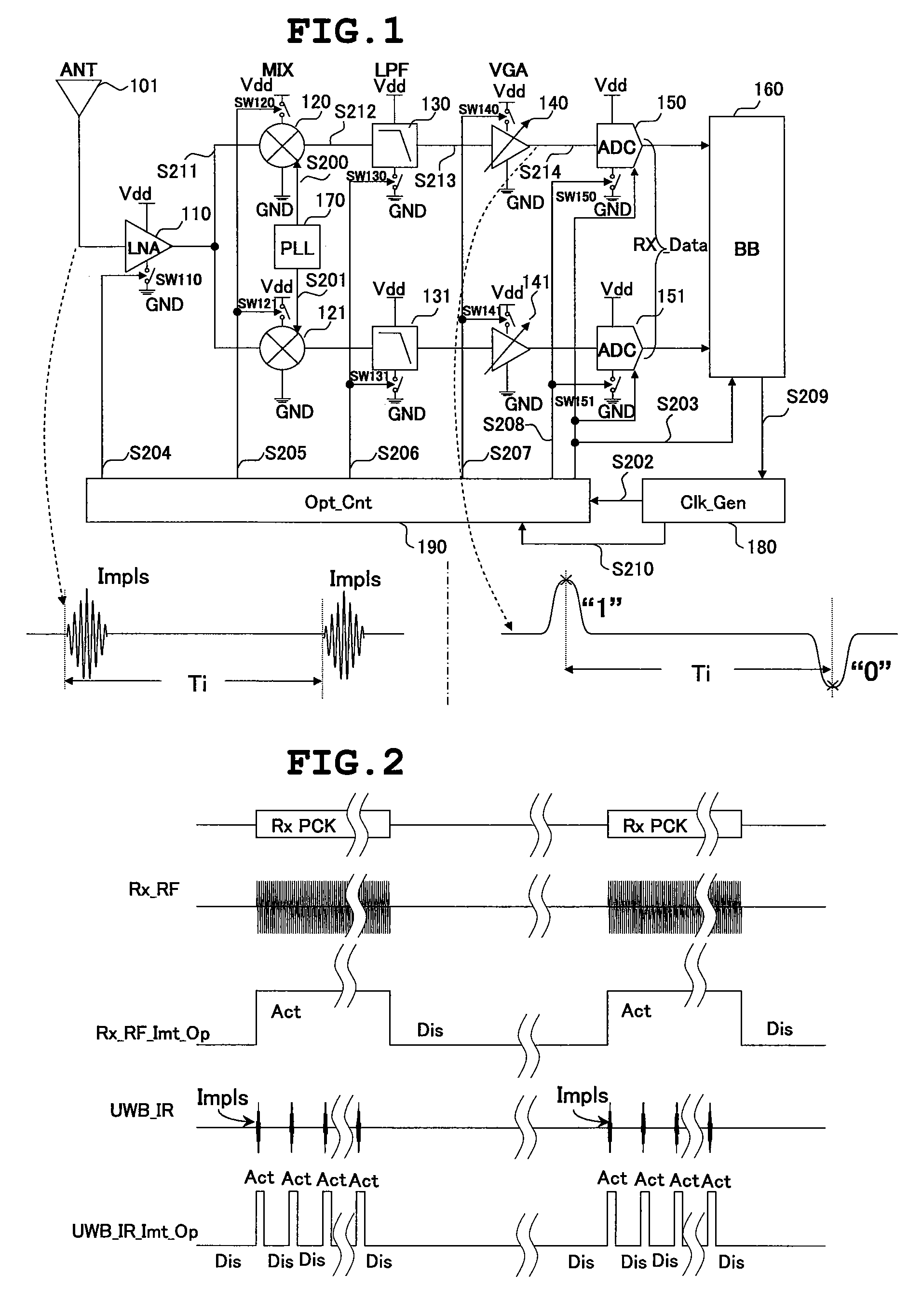
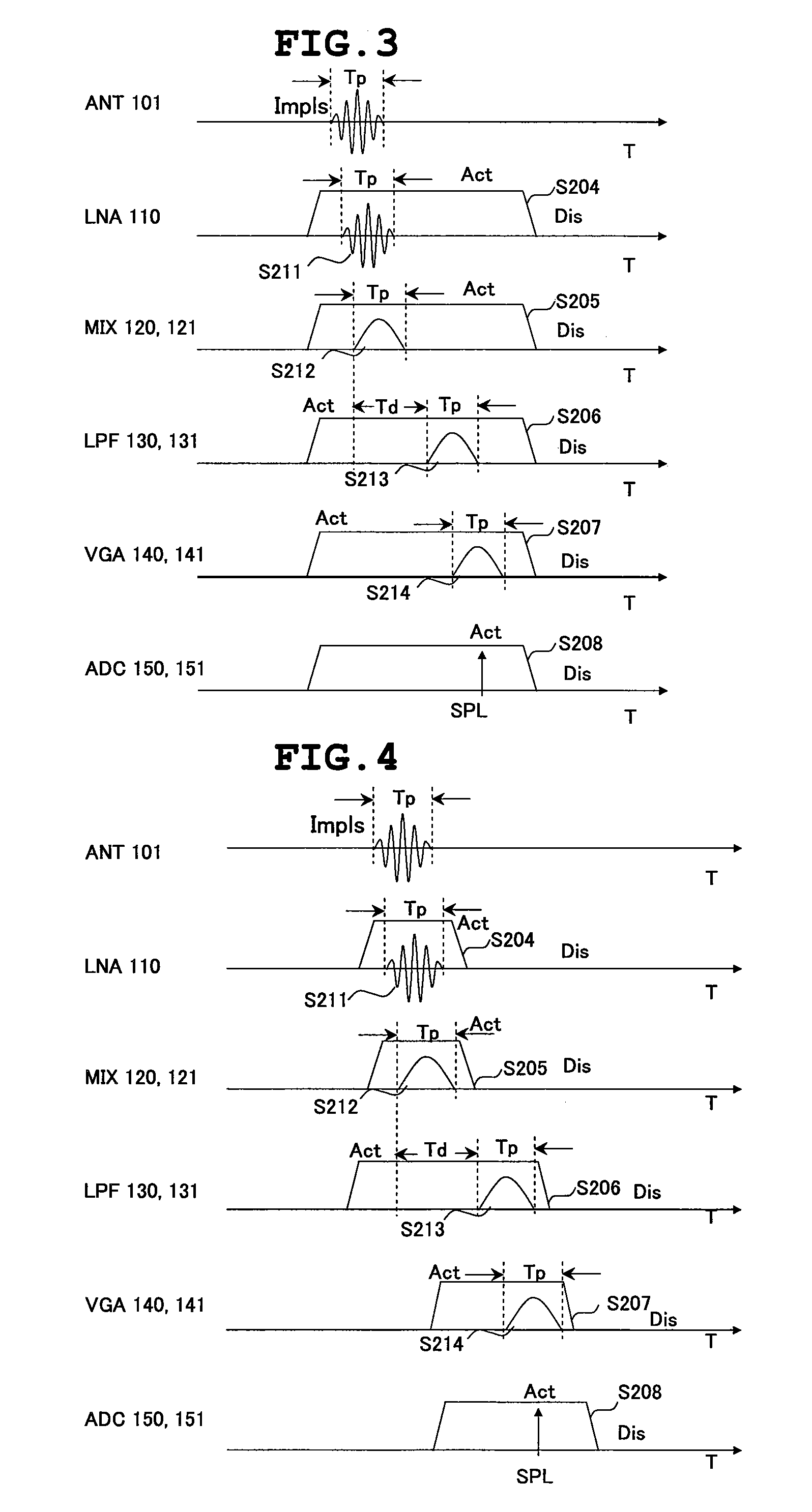
[0077]FIG. 1 is a block diagram showing a structure of a receiver for the UWB-IR radio communication according to a first embodiment of the present invention.
[0078]A time width of an impulse signal (Impls) of the UWB-IR radio communication received by the receiver for the UWB-IR radio communication according to this embodiment is about 2 nano-seconds and an interval Ti between the impulse signal Impls and the impulse signal Impls is about 30 nano-seconds. A frequency spectrum of the impulse signal Impls is an ultra-high frequency band signal with a center frequency of about 4 GHz and a frequency band of about 500 MHz. The receiver for the UWB-IR radio communication according to this embodiment includes a reception antenna (ANT) 101, a low noise amplifier (LNA) 110, mixers (MIX) 120 and 121, low-pass filters (LPF) 130 and 131, variable gain amplifiers (VGA) 140 and 141, analog-to-digital converters (ADC) 150 and 151, a baseband process...
second embodiment
[0116]FIG. 12 is a block diagram showing an example of a structure of a receiver for the UWB-IR radio communication according to a second embodiment of the present invention. Explanations of components common to the first embodiment are omitted.
[0117]The receiver according to the second embodiment includes the reception antenna 101, the low noise amplifier 110, the mixers 120 and 121, low-pass filters 132 and 133, variable gain amplifiers 142 and 143, the analog-to-digital converters 150 and 151, a baseband processing unit 161, a phase locked loop 170, the clock generating unit 180, and an operation-timing control unit 193.
[0118]A frequency spectrum of an impulse signal in the UWB-IR radio communication is an ultra-high frequency and signal with a center frequency of about 4 GHz and a frequency bandwidth of about 500 MHz as described above. However, the frequency bandwidth of about 500 MHz in the UWB-IR radio communication may be different depending on laws and regulations and radio...
third embodiment
[0134]FIG. 16 is a block diagram showing an example of a structure of a receiver for the UWB-IR radio communication according to a third embodiment of the present invention. Explanations of components common to the first and second embodiments are omitted.
[0135]The receiver according to the third embodiment includes the reception antenna 101, the low noise amplifier 110, the mixers 120 and 121, the low-pass filters 130 and 131, the variable gain amplifiers 140 and 141, analog-to-digital converters 152 and 153, a baseband processing unit 162, the phase locked loop 170, the clock generating unit 180, and an operation-timing control unit 195.
[0136]The operation-timing control unit 195 outputs, on the basis of a control signal S216 from the baseband processing unit 162, the clock signals S203, S205, S206, and S207 to the low noise amplifier 110, the mixers 120 and 121, the low-pass filters 130 and 131, and the variable gain amplifiers 140 and 141 and outputs clock signals S217, S218, an...
PUM
 Abstract
Description
Claims
Application Information