
Conductive polymer patterned electrode for pacing

a conductive polymer and electrode technology, applied in the field of pacing electrodes, can solve the problems of reducing the size of the electrode, reducing the blood circulation, and not being able to reduce the energy delivered too far,

Active Publication Date: 2008-03-20
CARDIAC PACEMAKERS INC
View PDF20 Cites 32 Cited by
  • Summary
  • Abstract
  • Description
  • Claims
  • Application Information

AI Technical Summary

Problems solved by technology

Such arrhythmias result in diminished blood circulation.
The energy delivered cannot be reduced too far, however, as a critical amount of current is required for pacing.
Furthermore, reducing the size of the electrode is not necessarily an optimal solution as then the electrode may be too small to properly and securely fix to the heart.
Moreover, smaller electrodes may have reduced sensing capacity.
Electrical current passed through these leads, however, may cause undesired chemical reactions such as water electrolysis, oxidation of soluble species, reactions that result in the formation of gases, and metal dissolution from the electrode.
The non-ideal biocompatibility of the metals used to make electrodes may therefore waste the energy provided to the electrode and result in decreased efficiency.
In addition, the electric performance may be affected by the geometry of the electrode itself.

Method used


Image

  • Conductive polymer patterned electrode for pacing
  • Conductive polymer patterned electrode for pacing
  • Conductive polymer patterned electrode for pacing

Examples


example 1

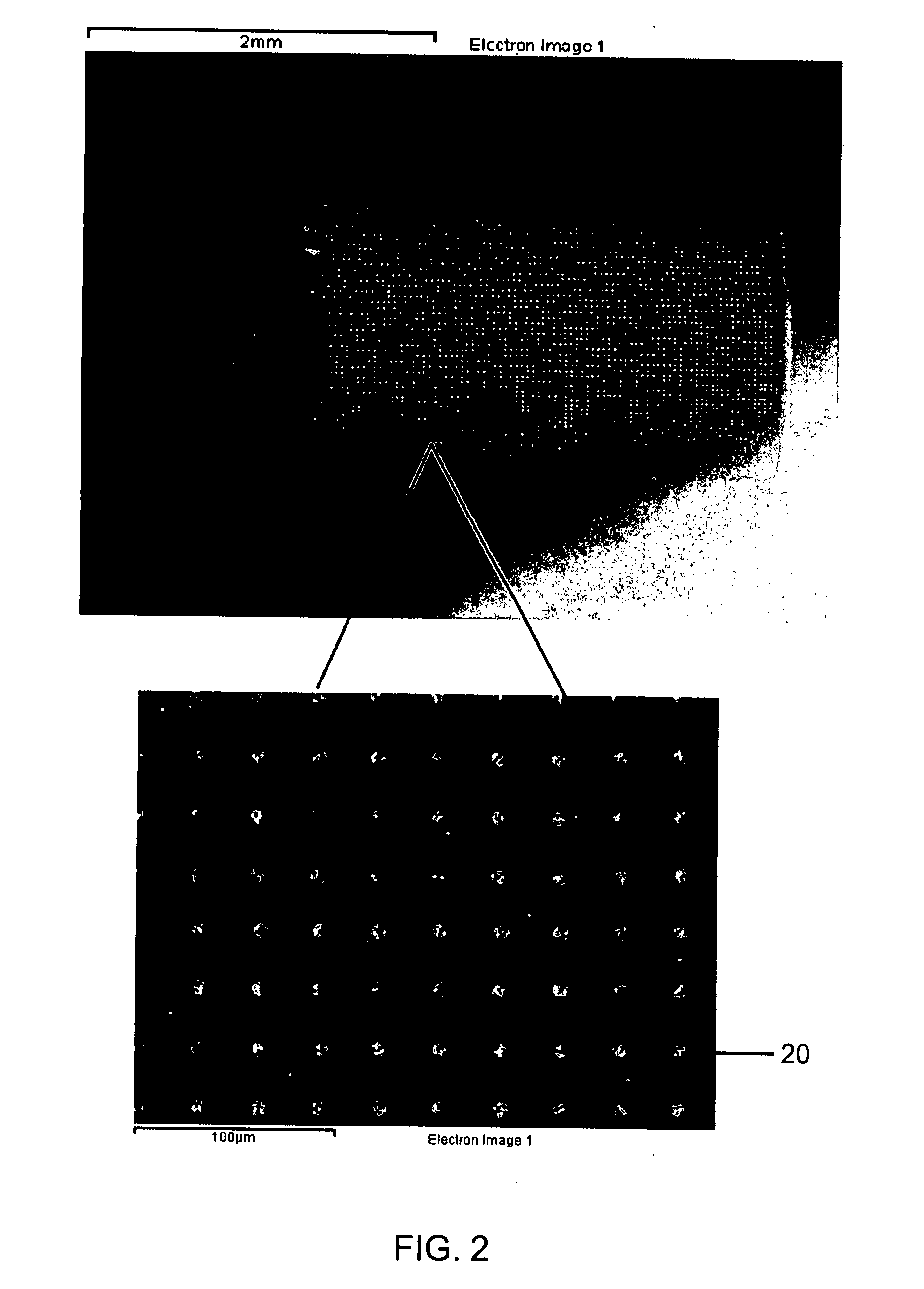
[0043]In a first example Parylene may be pattern coated on the surface of the electrode. As previously discussed, Parylene is an insulative polymer. In the present example the Parylene was coated on a platinum iridium ring by vapor deposition using methods known to those in the art. The resultant Parylene coating was about 5 μm thick. In alternative embodiments the coating may be from less than 1 μm to as much or more than 25 μm thick. The Parylene formed a complete coating over the ring and was then patterned by laser etching to form surfaces as shown in FIGS. 2 and 3. In FIG. 2, the patterning was done by creating specific holes 20 in the Parylene coating to expose the platinum iridium ring. FIG. 3 illustrates patterned trenches 30 in the Parylene coating parallel to the long axis of the ring. In further embodiments, patterned trenches may go circumferentially around the ring. In still further embodiments, any pattern may be made in the Parylene layer by the laser. The laser etchi...

example 2

[0047]In a second embodiment the electrode was pattern coated with polypyrrole. Polypyrrole is a conductive polymer. The application of the polypyrrole was accomplished by dissolving pyrrole in a solution at 0.1 M with a KCl dopant at 0.1 M and electrochemically depositing the pyrrole on a platinum iridium ring electrode dipped in the solution. The coating was applied to a thickness of about 5 μm but in further embodiments may be up to or more than about 25 μm. The coating was then laser etched to expose the platinum iridium ring to form holes 40 in the pattern illustrated in FIG. 4. In further embodiments the concentration of the pyrrole in the solution may be varied as desired, for example, utilizing concentrations up to or more than 0.5 M.

[0048]The pattern coated ring was then tested by cyclic voltammetry versus a platinum ring coated with iridium oxide. As illustrated in FIG. 6, the platinum ring with the iridium oxide coating had a relatively small trace. The trace was signific...


PUM


Abstract

The present invention is an apparatus and method for making a polymer patterned electrode for cardiac pacing and sensing. The electrode surface includes a polymer overlayed on an electrode. The polymer layer is patterned to form an electrode surface consisting of a polymer and a conductive metal surface. The electrode can be made of a high or low impedance electrode by changing the conductivity of the polymer. Furthermore, the electrode surface texture can be optimized with a micro pattern that may enhance the biocompatibility. The polymer may be conductive or insulative.

Description

FIELD OF THE INVENTION[0001]The present invention relates to pacing electrodes. More specifically, the present invention is an apparatus and method for making a conductive polymer patterned electrode for cardiac pacing and sensing.BACKGROUND OF THE INVENTION[0002]When functioning properly, the human heart maintains its own intrinsic rhythm and is capable of pumping adequate blood throughout the body's circulatory system. However, some people have irregular cardiac rhythms, referred to as cardiac arrhythmias. Such arrhythmias result in diminished blood circulation. One manner of treating cardiac arrhythmias includes the use of a cardiac rhythm management system. Such systems may be implanted in a patient to deliver electrical pulses to the heart.[0003]Cardiac rhythm management systems include, for example, pacemakers (also referred to as “pacers”), defibrillators (also referred to as “cardioverters”) and cardiac resynchronization therapy (“CRT”) devices. These systems use conductive ...

Claims


Application Information

Patent Timeline
IPC IPC(8): A61N1/05A61B5/296
CPCA61N1/0568A61N1/056
Inventor JIANG, XIANGCHUNELY, KEVIN J.POLKINGHORNE, JEANNETTE C.
Owner CARDIAC PACEMAKERS INC
Learn More