Device and method for controlling changing operation of on-load tap changer

a technology of changing operation and device, which is applied in the direction of motor/generator/converter stopper, dynamo-electric converter control, machine/engine, etc., can solve the problems of small time difference for changing operation, short circuit between taps, and difficulty in adjusting the plurality of tap changers

Inactive Publication Date: 2008-03-27
MITSUBISHI ELECTRIC CORP
View PDF7 Cites 17 Cited by
  • Summary
  • Abstract
  • Description
  • Claims
  • Application Information

AI Technical Summary

Benefits of technology

[0020]The present invention is directed to a solution to the above-described problems and it is an object of the invention to provide a device and method for controlling the changing operation of an on-load tap changer that interrupts current surely passing...

Problems solved by technology

However, if the load connected to the transformer is special, for example if power is supplied to a load such as an AC electric railcar or a flicker, or if a plurality of on-load tap changing transformers are operated in parallel, the following disadvantage is encountered.
At worst, if the arc cannot be extinguished before the main contact is closed on the next tap side, the arc current is passed, which could give rise to a serious accident such as short-circuiting between the taps.
However, it would be difficult to adjust the plurality of tap changers to be in the same timing for structural reasons, and very small time difference for changing operation is tolerated.
At worst, the current could continue to be passed before the main contact is closed on the next tap side, w...

Method used


Image

  • Device and method for controlling changing operation of on-load tap changer
  • Device and method for controlling changing operation of on-load tap changer
  • Device and method for controlling changing operation of on-load tap changer

Examples


first embodiment

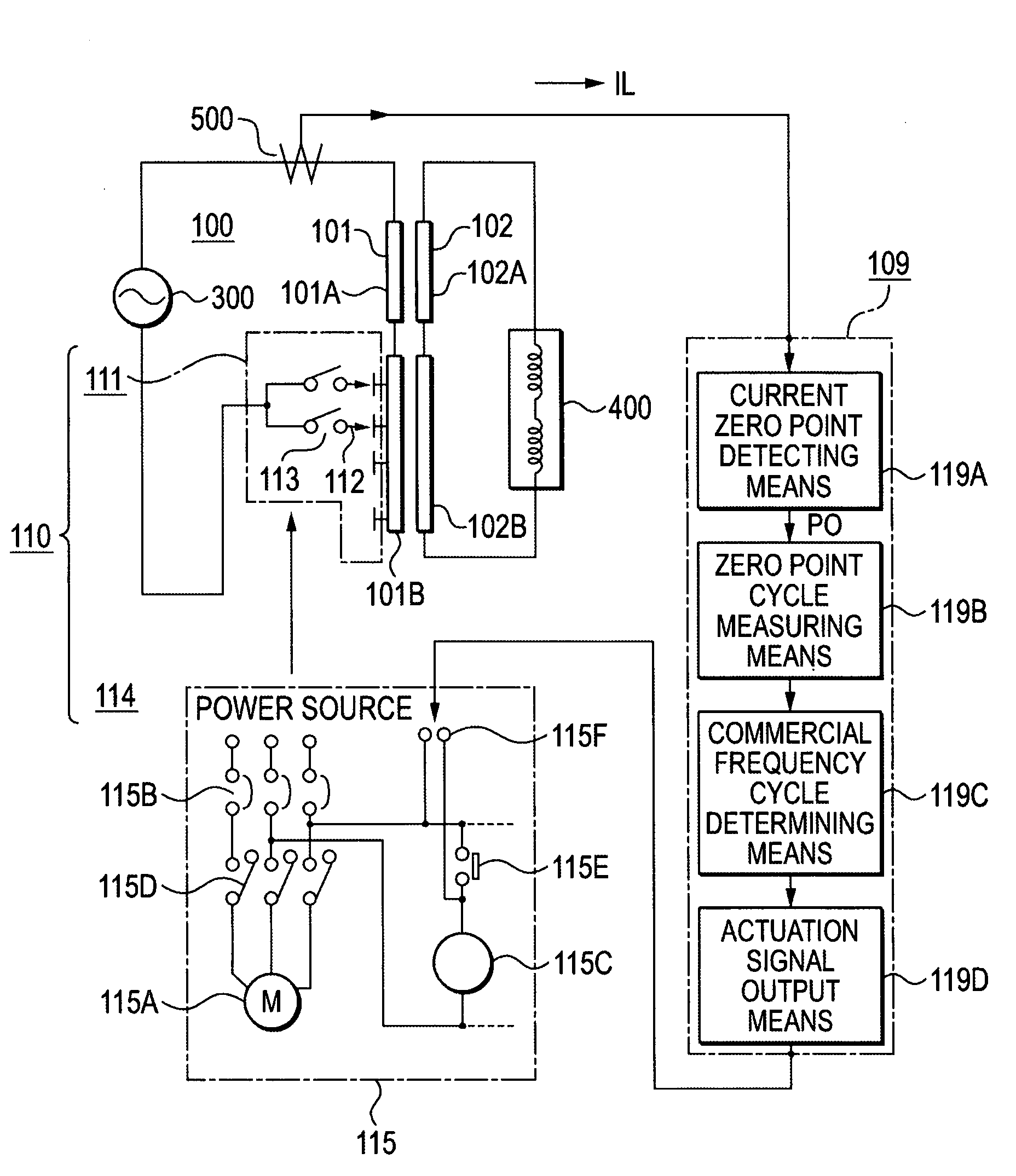
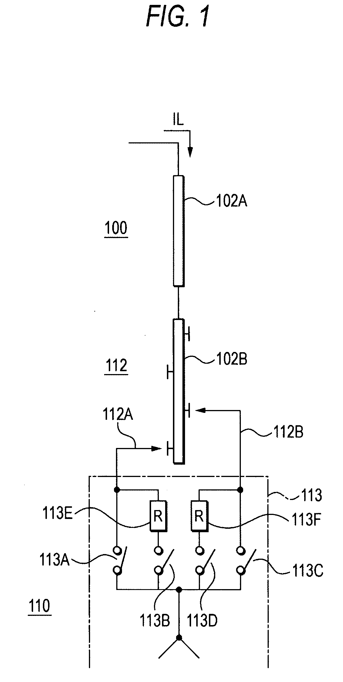
[0049]FIG. 1 is a diagram of a general example of a resistor type on-load tap changer (hereinafter simply as “LTC”). FIG. 1 shows a one-phase part on the secondary side of a three-phase transformer in a star connection. The transformer 100 includes a secondary side main winding 102A, a secondary side tap winding 102B and an LTC 110 that carries out tap changing to the secondary side winding 102B.

[0050]The LTC 110 includes a tap selector 112 having an odd-number side tap selector 112A and an even-number side tap selector 112B and a diverter switch 113 connected to the tap selector.

[0051]The diverter switch 113 includes an odd-number side main contact 113A, an odd-number side resistor contact 113B, and an odd-number side current limiting resistor 113E connected to the odd-number side tap selector 112A, and an even-number side main contact 113C, an even-number side resistor contact 113D, and an even-number side current limiting resistor 113F connected to the even-number side tap select...

second embodiment

[0071]According to a second embodiment, as a method of controlling the changing operation of LTCs when transformers are operated in parallel, the shaft alignment position is adjusted so that the operation positions of the diverter switches of the LTCs are not in coincidence at the connecting positions of coupling shafts that mechanically couple the LTCs and motor operation mechanisms that drive the LTCs. In this way, transient current superposed with DC current in the diverter switch in each of the LTCs can be prevented from being interrupted.

[0072]FIG. 8 is an equivalent circuit diagram of two LTC transformers operated in parallel, and FIGS. 9A to 9C show the waveforms of current in the equivalent circuit in FIG. 8.

[0073]In FIG. 8, 300 represents an AC power supply, 100 and 200 represent the LTC transformers operated in parallel, 110 represents an LTC operated prior to the other, 210 represents a succeeding LTC that operates delayed in time from the preceding LTC 110, and 400 repre...

third embodiment

[0100]According to the method of controlling the changing operation according to the second embodiment described above, the coupling positions of the output shafts of the motor operation mechanisms and the LTC main bodies are shifted so that the operation positions of the plurality of LTCs are not in coincidence. As will be described, according to a third embodiment, the same function is achieved by changing the point to start the motor operation of a plurality of motor operation mechanisms.

[0101]FIG. 19 is a diagram of the configuration of motor circuits that drives motor operation mechanisms according to the third embodiment. In a motor circuit 115 that drives the motor operation mechanism of an LTC 110 and a motor circuit 215 that drives the motor operation mechanism of an LTC 210 operated in association with the LTC 110, timers 115G and 215G are connected to the input power supplies of the motor circuits 115 and 215, respectively, the timing contacts 115H and 215H of the timers ...


PUM


Abstract

A device and method for controlling the changing operation of an on-load tap changer (LTC) that interrupts current surely passing the current zero point of a commercial frequency and prevents a serious accident such as short-circuiting between taps caused by an interruption failure in any operation environment with any kinds of consumer loads and either in a single or parallel arrangement are provided. The device includes a current zero point detecting unit that detects a zero point in the waveform of current passed through an LTC, a current zero point cycle measuring unit that measures the cycle of the current zero point detected by the current zero point detecting unit, a commercial frequency determining unit that generates an output signal when the cycle of the current zero point measured by the current zero point cycle measuring unit corresponds to a commercial frequency, and an actuation signal output unit that outputs an actuation signal used to have the LTC carry out tap changing operation in response to the output signal of the commercial frequency cycle determining unit.

Description

BACKGROUND OF THE INVENTION[0001]1. Field of the Invention[0002]The present invention relates to a device and method for controlling the changing operation of an on-load tap changer that changes the tap of a transformer.[0003]2. Description of the Related Art[0004]It has been well known that the on-load tap changer changes the tap of a transformer in a load operation state to change and adjust the turn ratio of secondary winding / primary winding of the transformer, in other words, changes and adjusts the transformation ratio.[0005]The on-load tap changer is driven by a motor operation mechanism to operate. The mechanism responds to a remote actuation command from an automatic voltage regulating relay (normally provided in the main control room) that continuously monitors the voltage state of the load of the transformer or from an operator who monitors the operation state in the main control room. The mechanism then operates the on-load tap changer to regulate voltage at the secondary...

Claims


Application Information

Patent Timeline
IPC IPC(8): H02P23/00H02P1/26H01F29/04
CPCH02P13/06
Inventor GENKAWA, HITOSHI
Owner MITSUBISHI ELECTRIC CORP
Why Eureka
Try Eureka