Methods and Apparatus for Handheld Printing with Optical Positioning

a handheld printer and optical positioning technology, applied in the field of handheld printers, can solve the problems of inability to print jobs, user incomplete print jobs, and limited capabilities of sensor inputs, so as to facilitate manufacturing simplicity, improve computational efficiency, and minimize costs

Inactive Publication Date: 2008-03-27
LEXMARK INT INC
View PDF99 Cites 1 Cited by
  • Summary
  • Abstract
  • Description
  • Claims
  • Application Information

AI Technical Summary

Benefits of technology

[0009]Methods and apparatus further include handheld printers manipulated back and forth by an operator during use to print an image on a media. The image is printed with various actuators of an inkjet printhead and a controller correlates the location of the printhead to the image and causes printing by the actuators or not as a user maneuvers a housing of the printer. A position sensor, preferably optical, provides input to the controller. The sensor is also representatively an off-the-shelf type sensor to facilitate manufacturing simplicity and minimize costs. Its signal typifies a plurality of pixels (representing grayscale values of light reflected from the media) in a matrix frame indicating a current position frame and, over time, a previous position frame. The controller compares the two frames to find a presence of the previous position frame in the current frame, in turn, ascertaining a location of the printer and printhead. As before, the controller reduces a relative size of both frames before the step of comparing to improve computational efficiency, especially by way of speeding-up the process of evaluation. Specific reduction techniques contemplate converting a matrix frame of pixels in m×n form indicative of a previous and current location, where m and n may equal one another, into smaller matrices, including one-dimensional and square matrix forms. Possible search areas within the current frame showing a presence of the previous frame utilize knowledge about the previous movement history of the printer to predict where-to-look locations.

Problems solved by technology

Yet, sensor inputs are sometimes limited in their capabilities and print jobs are interrupted due to lost or inaccurate printer location calculations.
If printing quits, users have incomplete print jobs.
If locations are guessed, print quality suffers.
In either, poor results are obtained.
In the event printer locations are not completely lost, but simply inaccurate, print quality suffers because of inappropriately placed ink print patterns being deposited on the media.
Error accumulation also adds to the problem of ink placement.
Appreciating typical optical sensors have numerous data pixels, correlation becomes computationally extensive because comparisons of large amounts of pixel data to other large amounts of pixel data require large storage and processing power.

Method used


Image

  • Methods and Apparatus for Handheld Printing with Optical Positioning
  • Methods and Apparatus for Handheld Printing with Optical Positioning
  • Methods and Apparatus for Handheld Printing with Optical Positioning

Examples


Embodiment Construction

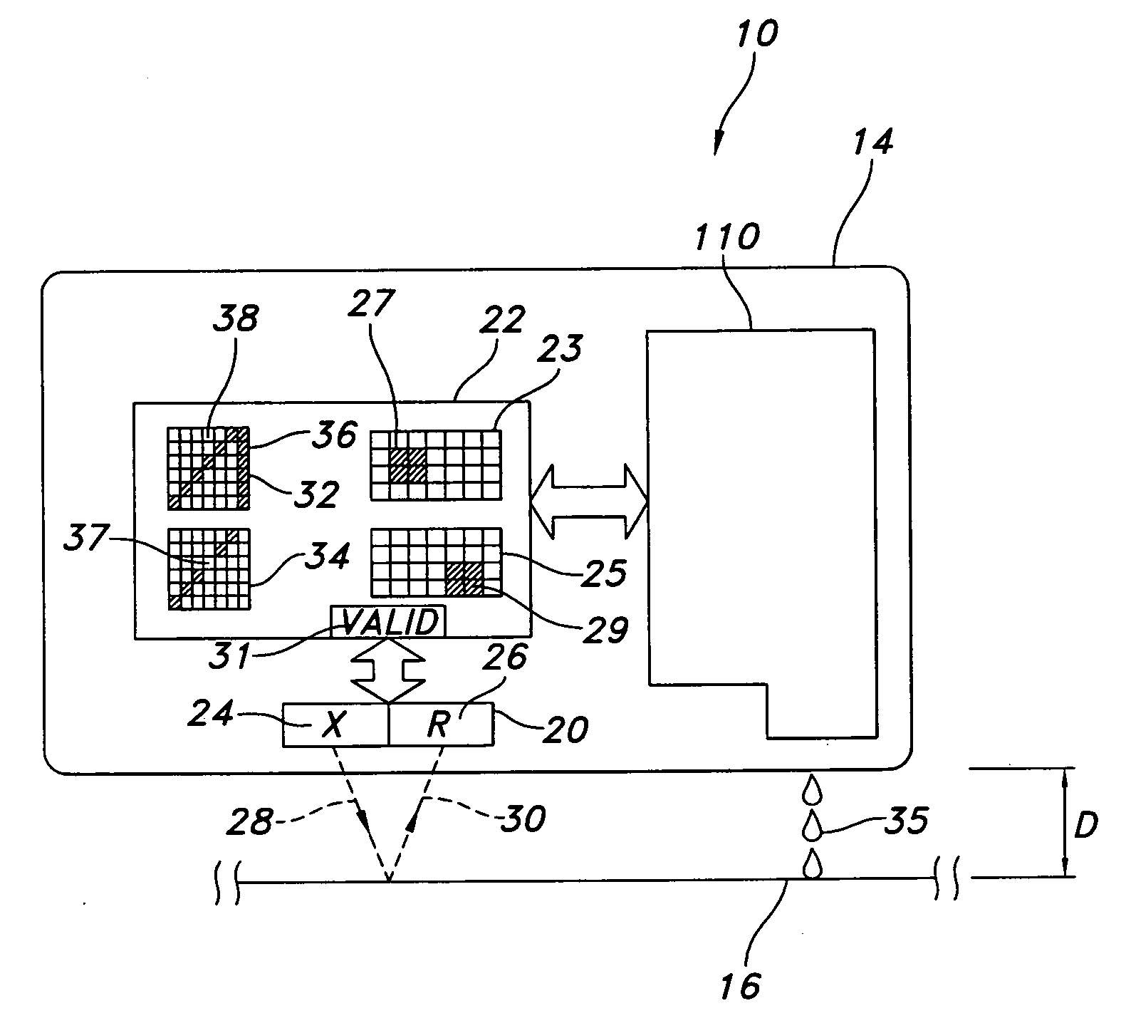
[0034]In the following detailed description of the preferred embodiments, reference is made to the accompanying drawings that form a part hereof, and in which is shown by way of illustration, specific embodiments in which the invention may be practiced. These embodiments are described in sufficient detail to enable those skilled in the art to practice the invention and like numerals represent like details in the various figures. Also, it is to be understood that other embodiments may be utilized and that process, mechanical, electrical, architectural, software and / or other changes may be made without departing from the scope of the present invention. In accordance with the present invention, a handheld printer for printing with optical positioning, especially by way of optical position sensors, is hereafter described.

[0035]Preliminarily, however, skilled artisans will appreciate that an iterative process occurs in evaluating signals (and attendant data) from position sensors in a ha...


PUM


Abstract

Methods and apparatus include a handheld printer manipulated by an operator to print an image on a media. A controller correlates a location of a printhead to the image and causes printing or not. A position sensor provides input to the controller. Its signal typifies pixels in a matrix frame indicating a current position frame and, over time, a previous position frame. The controller compares the two frames to find a presence of the previous in the current. To improve computational efficiency, the controller reduces a relative size of both frames before comparing. Specific reduction techniques contemplate converting a matrix frame of pixels indicative of previous and current locations into smaller matrices, including one-dimensional forms. Possible search areas within the current frame to look for the previous frame utilize knowledge about the movement history of the printer. Position sensor signal validity and controller architectures are other noteworthy features.

Description

[0001]This application claims priority to and benefit of U.S. Provisional Patent Application Ser. No. 60 / 827,117, filed Sep. 27, 2006, entitled “Optical Navigation System using Reduced Reference and Sample Objects and Enhanced Target Tracking Method.”FIELD OF THE INVENTION[0002]Generally, the present invention relates to handheld printers. Particularly, it relates to improving print quality in handheld printers of the type able to print in random motion patterns. In one aspect, sensors optically provide position information of the printer regardless of user movement patterns. In another, particular printer control architectures are contemplated. Still other aspects relate to computational efficiencies relative to position sensor signals. Other noteworthy features relate to assessing validity of position sensor signals.BACKGROUND OF THE INVENTION[0003]As is known, handheld printers afford mobile convenience to users. Unlike their immobile or stationary counterparts, users determine t...

Claims


Application Information

Patent Timeline
Patent Type & Authority Applications(United States)
IPC IPC(8): B41J3/00
CPCB41J3/36H04N1/047H04N1/195H04N2201/04712H04N2201/04734H04N2201/04737
Inventor GRANDEZA, MICHELIN DE LA PENAVALENTUS, VINCENT PETER CRISOSTOMOREED, WILLIAM HENRY
Owner LEXMARK INT INC
Why Eureka
Try Eureka