Ultrasound diagnostic apparatus and a medical image-processing apparatus

a diagnostic apparatus and ultrasound technology, applied in tomography, applications, instruments, etc., can solve the problems of complex operation, time-consuming, and inability to comprehensively observe the condition of the left ventricle, so as to reduce the time of examination, facilitate the observation of images, and shorten the examination time

Active Publication Date: 2008-03-27
TOSHIBA MEDICAL SYST CORP
View PDF6 Cites 65 Cited by
  • Summary
  • Abstract
  • Description
  • Claims
  • Application Information

AI Technical Summary

Benefits of technology

[0128]Actions and advantageous effects of the ultrasound diagnostic apparatus 1 are described. When obtaining the image data for the tomographic image (MPR image) of biological tissue such as a heart, the ultrasound diagnostic apparatus 1 stores, in the information memory 6, the cross-sectional-position information D (D1) showing the cross-sectional position of that tomographic image. Additionally, when obtaining the image data for a new tomographic image of the biological tissue, the ultrasound diagnostic apparatus 1 obtains the image data for new tomographic image corresponding to the cross-sectional position shown in the cross-section location information D of the image data for the tomographic image having been obtained in the past and then displays this new tomographic image and the past tomographic image side by side.
[0129]In particular, in a case in which a stress echocardiography is performed by obtaining volume data from the three-dimensional ultrasonic scan, the ultrasound diagnostic apparatus 1 operates, based on the cross-sectional-position information D for the MPR image stored by the examination in the past phase, to display at real time the MPR image for the cross-section corresponding to the MPR image for this past phase.
[0130]According to the ultrasound diagnostic apparatus 1, in the examination for observing the time-elapsed changes in biological tissue, it is possible to automatically obtain the tomographic image for the cross-sectional position corresponding to the tomographic image observed in the past examination, and therefore easily obtain the tomographic images in the same cross-sectional position of the biological tissue. Examples of such examination include a stress echocardiography, an observation of the clinical course, a pre-treatment / post-treatment observation (periodical medical examination such as a prognostic follow-up), and a preoperative / postoperative observation.
[0131]Additionally, according to the ultrasound diagnostic apparatus 1, the tomographic image obtained in the past examination can be placed side by side with the tomographic image obtained in new examination in a condition in which the mutual cross-sectional positions are matched, which makes it possible to comparatively observe these images easily.
[0132]Additionally, the user can match the cross-sectional position of the new tomographic image with the cross-sectional position of the past tomographic image by simply adjusting the manner of placement of the ultrasonic probe 2 as needed. This makes it possible to easily perform an examination such as a stress echocardiography examination for observing the time-elapsed changes in biological tissue. It is also possible to shorten the examination time.
[0133]Furthermore, according to the ultrasound diagnostic apparatus 1, a plurality of pairs of the past tomographic image and the new tomographic image, which are matched with the cross-sectional position, can be simultaneously displayed as shown in FIG. 6 and FIG. 7. That enables the user to perform a comprehensive diagnosis, while comparative observation of the images of various cross-sectional positions of the biological tissues.

Problems solved by technology

However, regarding a conventional ultrasound diagnostic apparatus the following problems are pointed out.
Firstly, there has been a problem in which stress echocardiography using two-dimensional images needs to variously change the way in which the ultrasonic probe is placed on the subject in order to obtain multiple images as described above, resulting in a complicated and long-time examination.
Secondly, although an image of the short-axis viewal view of the left ventricle is suitable for the observation of heart wall motion, it is possible in stress echocardiography using two-dimensional images, to obtain only short-axis tomographic images at the papillary muscle level, so that there has been a problem in which the condition of the left ventricle cannot be observed comprehensively.
However, there has been a problem in which this operation is highly complicated and time consuming.
Additionally, because there has been no means for comparative observation by displaying both a past MPR image and a new MPR image, it has been particularly troublesome and time consuming to match a cross-sectional position of a past MPR image with a cross-sectional position of a new MPR image.
Furthermore, in the comparative observation, it is preferable to observe tomographic images at the same cross-section for each phase, but it has been difficult to set the same cross-section for each phase in a conventional configuration.
However, it is not possible to verify the manner of placement of the ultrasonic probe until an image is displayed for viewing.
Therefore, it has been particularly troublesome and time consuming to determine the manner of placement of an ultrasonic probe.
In addition, even in the case of observation of the clinical course, preoperative / postoperative observation, and the like, it has been difficult to designate the same cross-section for each timing when tomographic images based on volume data obtained at different timings are comparatively observed.

Method used


Image

  • Ultrasound diagnostic apparatus and a medical image-processing apparatus
  • Ultrasound diagnostic apparatus and a medical image-processing apparatus
  • Ultrasound diagnostic apparatus and a medical image-processing apparatus

Examples


first embodiment

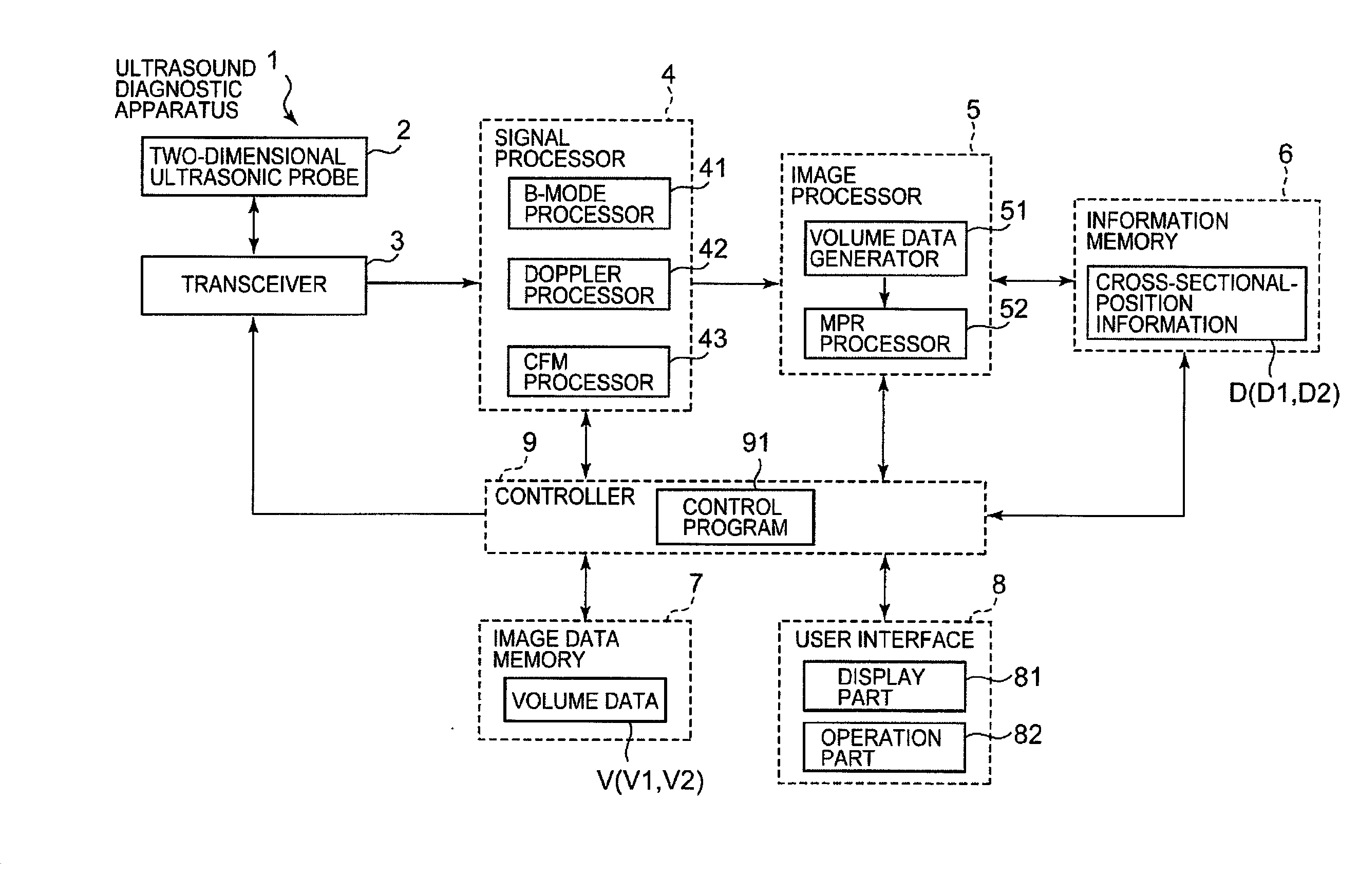
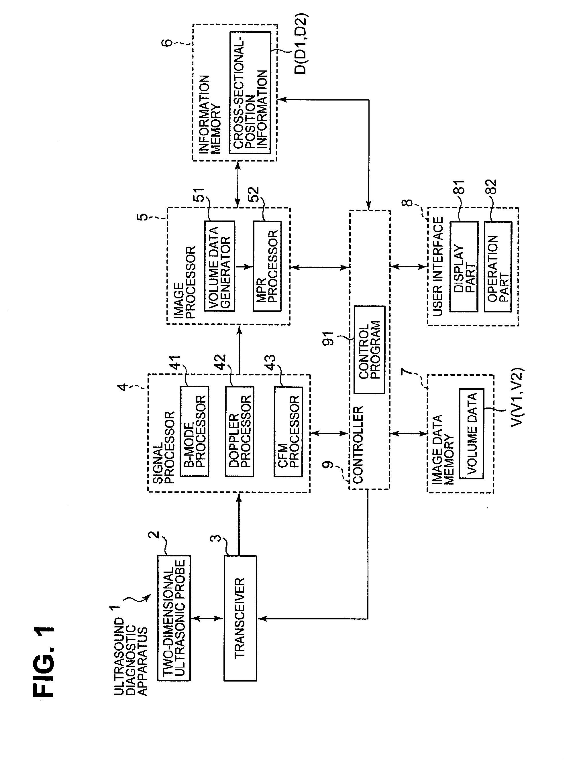
[0044]FIG. 1 illustrates an example of the entire configuration for the first embodiment of an ultrasound diagnostic apparatus according to the present invention. An ultrasound diagnostic apparatus 1 is an apparatus that is used, for example, for obtaining an image showing the shape of biological tissue such as a heart and an image showing a blood flow condition.

[Apparatus Configuration]

[0045]The ultrasound diagnostic apparatus 1 comprises a two-dimensional ultrasonic probe 2, a transceiver 3, a signal processor 4, an image processor 5, an information memory 6, an image data memory 7, a user interface 8, and a controller 9. Specific examples for each part composing the ultrasound diagnostic apparatus 1 will be described below.

User Interface and Controller

[0046]First, the user interface 8 and the controller 9 will be described hereunder. A display part 81 and an operation part 82 are provided in the user interface 8.

[0047]The display part 81 corresponds to an example of a “display pa...

modification examples

[0134]It is possible to modify the ultrasound diagnostic apparatus 1 as described below.

modification example 1

[0135]In the above embodiment, the usage for the case of obtaining a new image at real time has been described, but it is not limited to this. For example, the present invention can also be applied to a case of comparative observation (review) of the images obtained at a plurality of different dates in the past (timing that is different in date or time).

[0136]In the case of comparison of the images obtained at two different dates, the image obtained at the earlier date may be referred to as a “past” image, where as the image obtained at the later date may be referred to as a “new” image.

[0137]Now, a review of the examination for observing the time-elapsed changes in biological tissue, such as stress echocardiography, is performed using, for example, a tomographic-image-comparing screen 4000 shown in FIG. 8. The tomographic-image-comparing screen 4000 includes display ranges 4001 to 4006 as in the case of the tomographic-image-comparing screen 3000 of FIG. 7. Additionally, the tomogr...


PUM


Abstract

An ultrasound diagnostic apparatus 1 comprises an ultrasonic probe 2 for transmitting the ultrasound while three-dimensionally scanning, and receiving ultrasound reflected from biological tissue, an image processor 5 (and a signal processor 4) for generating image data for an MPR image based on results received thereof, an information memory 6 for storing cross-sectional-position information D showing a cross-section of this MPR image, a display part 81, and a controller 9. The image processor 5 generates image data for the new MPR image for the relevant cross-sectional position, based on the cross-sectional position shown in the cross-sectional-position information D1 obtained when the MPR image was obtained in the past and the received results obtained by the new three-dimensional scan performed with the ultrasonic probe 2. The controller 9 causes the display part 81 to display the new MPR image.

Description

BACKGROUND OF THE INVENTION[0001]1. Field of the Invention[0002]The present invention relates to an ultrasound diagnostic apparatus and a medical image-processing apparatus. The ultrasound diagnostic apparatus is an apparatus that transmits ultrasound to the inside of a subject using an ultrasonic probe, and obtains medical images of the subject based on waves reflected therefrom. The medical image-processing apparatus is an apparatus for processing medical images obtained by the ultrasound diagnostic apparatus. In particular, the present invention relates to the art used for comparative evaluation of motor functions of the same biological tissue obtained at different timing.[0003]2. Description of the Related Art[0004]The ultrasound diagnostic apparatus has a merit whereby it is possible to observe an image instantly by a simple operation such as the operation of simply placing the ultrasonic probe in contact with a body surface. Thus, the ultrasound diagnostic apparatus has been w...

Claims


Application Information

Patent Timeline
Patent Type & Authority Applications(United States)
IPC IPC(8): A61B8/00
CPCA61B5/4884A61B8/06A61B8/0883A61B8/13A61B8/14A61B8/463A61B8/466A61B8/488A61B8/523A61B8/543G01S7/52074G01S15/8993A61B8/483
Inventor KAWAGISHI, TETSUYAABE, YASUHIKOHASHIMOTO, SHINICHIKATAGUCHI, MUNEKI
Owner TOSHIBA MEDICAL SYST CORP
Why Eureka
Try Eureka