
Optical biofilm therapeutic treatment

a biofilm and optical technology, applied in the field of biofilms, can solve the problems of increasing the treatment cost of patients, affecting the treatment effect of patients, and causing human and animal diseases, and achieve the effect of minimizing unwanted hyperthermia (heat and burning)

Inactive Publication Date: 2008-03-27
NOMIR MEDICAL TECH
View PDF10 Cites 26 Cited by
  • Summary
  • Abstract
  • Description
  • Claims
  • Application Information

AI Technical Summary

Benefits of technology

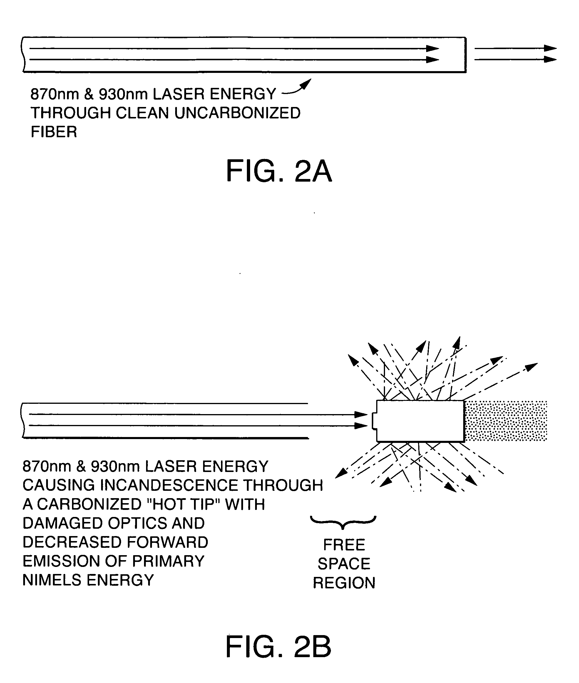
[0016] As mentioned previously, one exemplary biofilm consists of a matrix formed from exopolysaccharide (EPS), water and microbes in percentages of roughly 5% (EPS), 92% (water) and 3% (microbes). The EPS component is an extremely hydrated gel-like (mucinous) bio-polymer that creates a 3-dimensional structure of the biofilm. It is the EPS matrix that protects the microbes within the biofilm from attack by antimicrobial agents (antibiotics) and the immune system. Biofilms and diseased epithelium are highly permeable to Methylene Blue (MB) (and other dyes as described herein). In operation, the intense energy from the incandescent fiber of the therapeutic device of the disclosure is absorbed by MB molecules impregnating the biofilm. That absorbed energy is almost immediately converted to vibrational and rotational energy within the MB molecules. This heat raises the temperature of the MB or anything that is stained with MB.
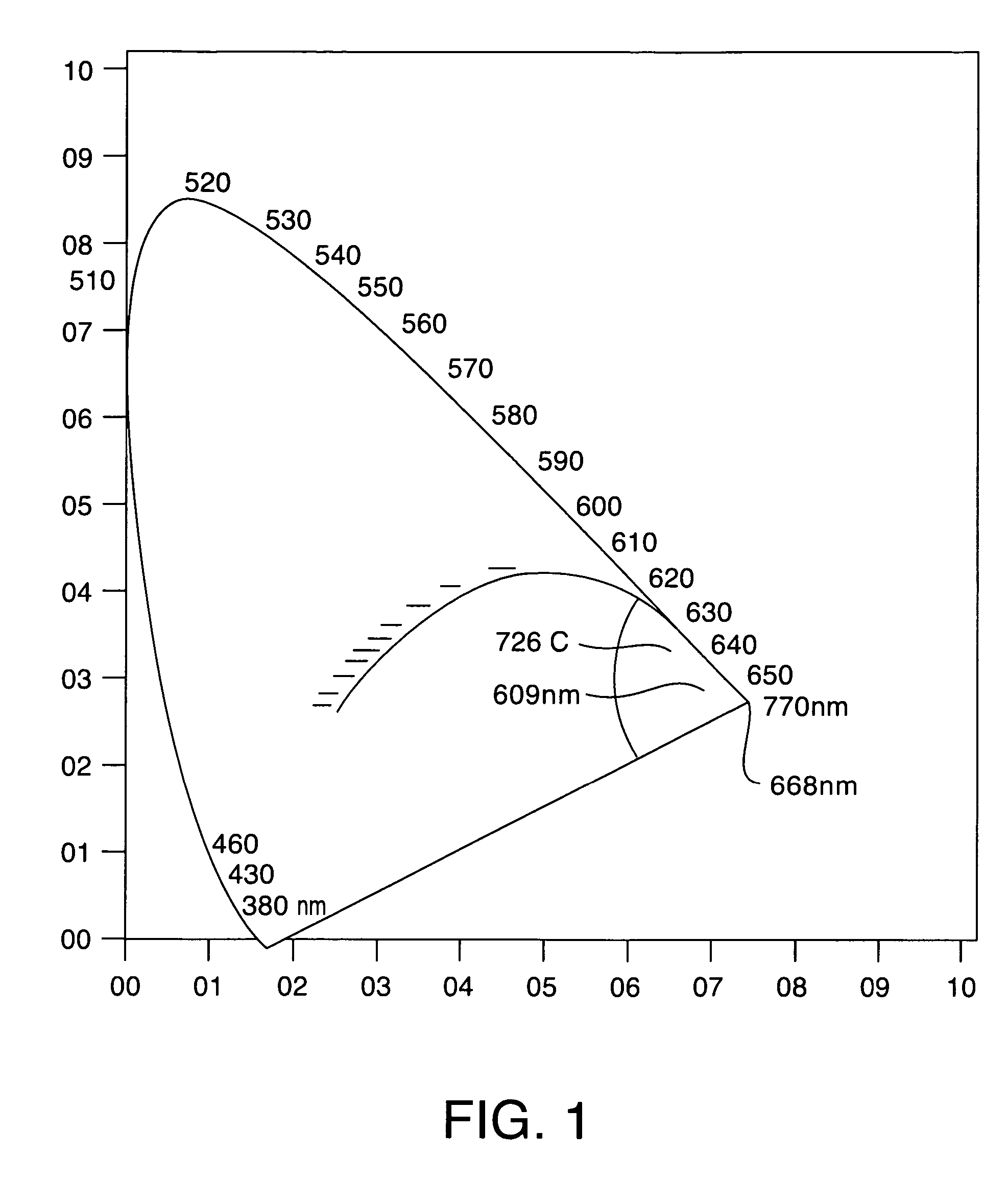
[0018] According to a further preferred embodiment of the present disclosure, the primary optical energy source is a Near Infrared Microbial Elimination Laser (NIMEL) system, which can include a dual wavelength solid state near-infrared diode laser system, specifically designed for the purpose of optical bacterial elimination, with minimal heat deposition to the tissue being irradiated. Such NIMELs wavelengths can be utilized to create free radicals such as singlet oxygen in targeted tissue to kill off or mitigate unwanted / undesired microbes (e.g., bacteria, fungus, etc.)
[0022] According to an exemplary embodiment of the present disclosure, an infected wound and / or implantable medical structure can be first treated with Targeted Biofilm Thermolysis (in accordance with the current disclosure) at the chromophore stained tissue / structure, which can include a biofilm. Then the thermalized biofilm and diseased tissue on the wound can be cleaned and debrided away. The cleaned wound can then treated with the primary photons from a NIMEL system at a subsequent time. Accordingly, the optical energy generated by the NIMEL system can irradiate or penetrate such a wound / tissue or device / structure, and kill any remaining microbes.
[0023] The NIMEL system described is capable of destruction of bacterial cells through the absorption by the bacterial cells of the unique laser energy, selectively in intracellular bacterial chromophores (colors). This can occur without any significant heat deposition. The NIMEL system is able to selectively destroy unwanted biological moieties to a sufficient depth (e.g., bacteria up to four centimeters in soft tissue), while minimizing unwanted hyperthermia (heat and burning) in tissue and surrounding area or medium.

Problems solved by technology

Because the polymer matrix of a biofilm usually offers resistance to the bacteria from antibiotics, host immune and defense systems, and conventional cleaning agents, biofilms that cause human and animal diseases are typically very difficult to be treated.
This not only causes a great difficulty for the patient, but increases the treatment cost of the patient.

Method used


Image

  • Optical biofilm therapeutic treatment
  • Optical biofilm therapeutic treatment
  • Optical biofilm therapeutic treatment

Examples


example 1

Treatment of an Infected Wound

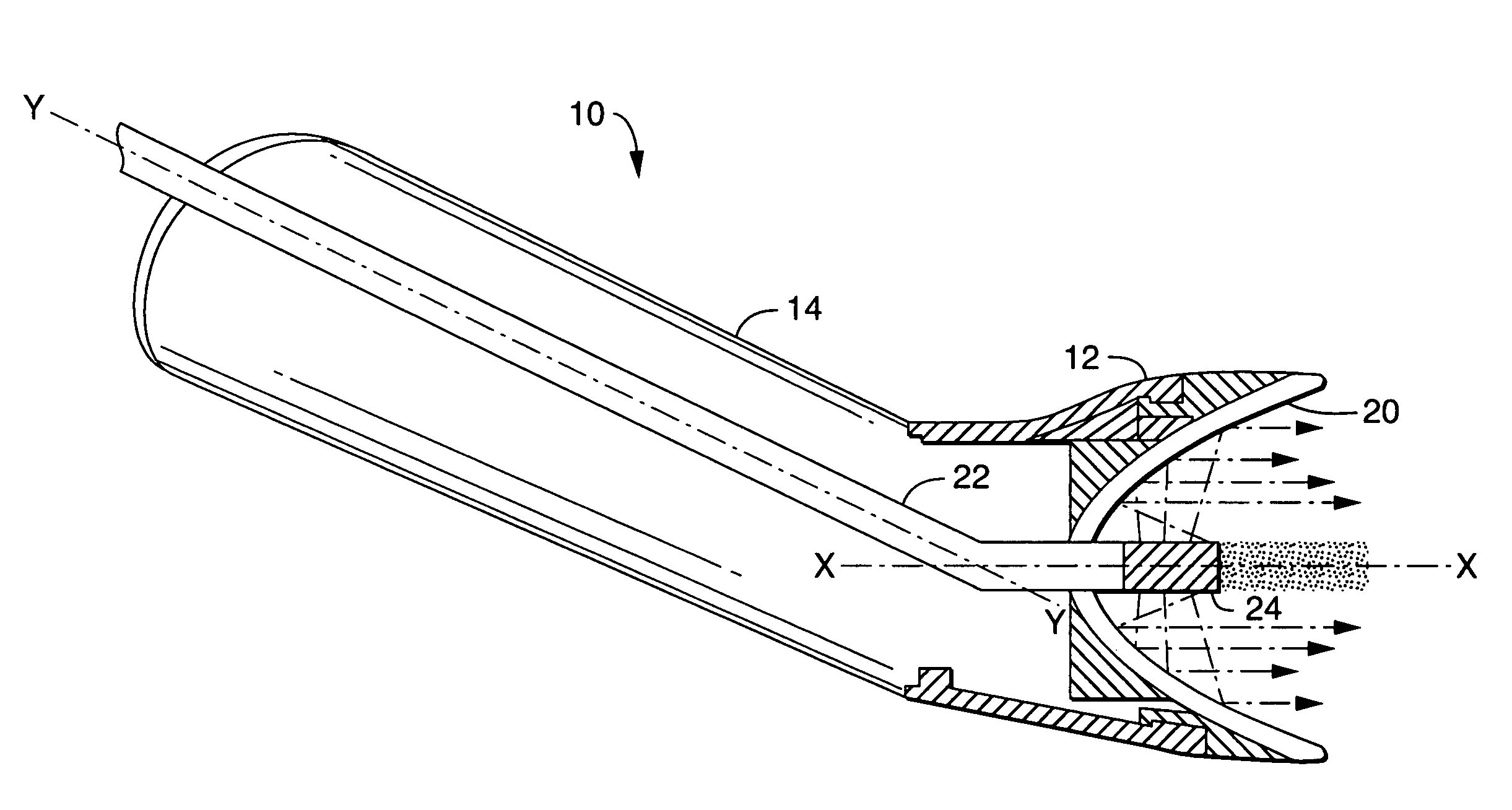
[0101] On day one of the treatment, the biofilm in the wound or foot-ulcer is dyed with Methylene Blue solution or equivalent, and the output power of a NIMEL system is increased enough to generate an “incandescent tip” in an optical therapeutic treatment device 10 for targeting live biofilms, as shown in FIG. 9. The incandescent energy generated at the incandescent tip is then applied to the target area. The area is then debrided and irrigated with the tissue debridement brush 40 as shown in FIG. 10.

[0102] On day two through seven of treatment, the optical power (i.e. the primary NIMEL photons with minimal heat deposition) of the NIMEL system is employed (through a different handpiece) to penetrate healing wound and kill any remaining bacteria, as shown in FIG. 11, thereby allowing tissue healing, with the dosimetry calculated with the algorithm disclosed above.

[0103] The patents, published applications, and scientific literature referred to herein ...


PUM


Abstract

Optical therapeutic treatment devices, systems, apparatus, methods, and techniques are disclosed. Embodiments can include a housing extending along a central axis X, an elongated fiber guide coupled to the housing and adapted to receive an optical fiber having a proximal end and a distal end, a reflector assembly within the housing and extending along the central axis X. The distal end of the optical fiber can includes a carbonized tip within the reflector assembly. The reflector assembly is adapted to reflect the optical energy emitted from the distal end and propagating radially with respect to the central is, so that the reflected optical energy propagates at least in part along a propagation axis parallel to the central axis. Embodiments can utilize free space optics / transmission. Further embodiments can utilize NIR radiation (e.g., including 870 and 930 nm) that is suitable to cause free radical formation in microbes.

Description

RELATED APPLICATIONS [0001] This application is a continuation-in-part of U.S. application Ser. No. 10 / 961,796 (as well as PCT Application Serial No. PCT / US2004 / 033431), filed 8 Oct. 2004, which claims the benefit of U.S. Provisional Application Ser. No. 60 / 509,685, filed 8 Oct. 2003; the contents of both of which applications are incorporated in their entireties herein by reference; this application further claims the benefit of U.S. Provisional Application Ser. No. 60 / 832,770 and U.S. Provisional Application Ser. No. 60 / 832,893, both filed 24 Jul. 2006, both of which application are incorporated in their entireties herein by reference.BACKGROUND [0002] The word “biofilm” is often used to describe a community of microorganisms that are enclosed in a mucinous like polymer matrix. Biofilms often consist of many species of bacteria and archaea (and can include fungus), which are typically all held together and protected by a matrix of excreted polymeric compounds. A common biofilm mat...

Claims


Application Information

Patent Timeline
IPC IPC(8): A61N5/06
CPCA61C1/0046A61N5/0601A61N5/0613A61N2005/067A61N2005/0644A61N2005/0659A61N2005/063A61N5/067
Inventor BORNSTEIN, ERIC
Owner NOMIR MEDICAL TECH
Learn More