Flexible vessel

a flexible, vessel technology, applied in the field of flexible vessels, can solve the problems of inability to precisely balance the load sharing between individual fibers, the potential point load induced source of chain reaction failure of interfaces, joints or seams, and the inability to ultimately bode well, so as to facilitate significant opportunity for vessel modularity and beneficial stress distribution

Active Publication Date: 2008-04-03
THIN RED LINE AEROSPACE
View PDF24 Cites 25 Cited by
  • Summary
  • Abstract
  • Description
  • Claims
  • Application Information

AI Technical Summary

Benefits of technology

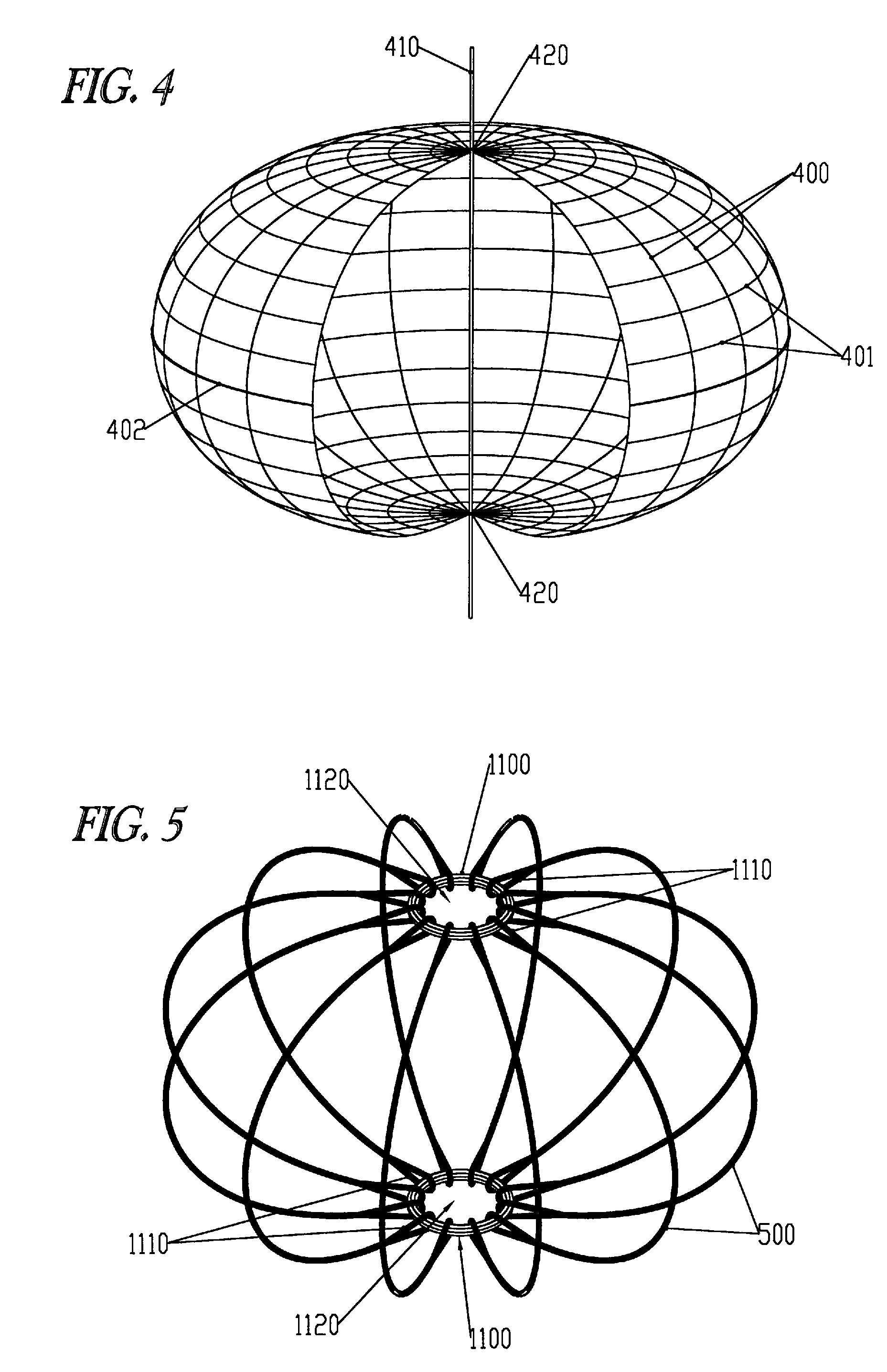
[0016]The vessel default provides a stable default geometry. The reliability provided by the default geometry can be further bolstered by incorporating at least one high modulus carrier layer into the barrier structure to eliminate excessive bulging which could lead to undesirable meridional stress in the oversized barrier. By precluding meridional tautness in the barrier, the vessel of the invention substantially enjoys statically determinate global stress distribution. The combination of an inherently stable deployed configuration and predictable global stress distribution is instrumental in providing a reliable, versatile and robust vessel well adapted to the operational functionalities required for deployment in space environments.
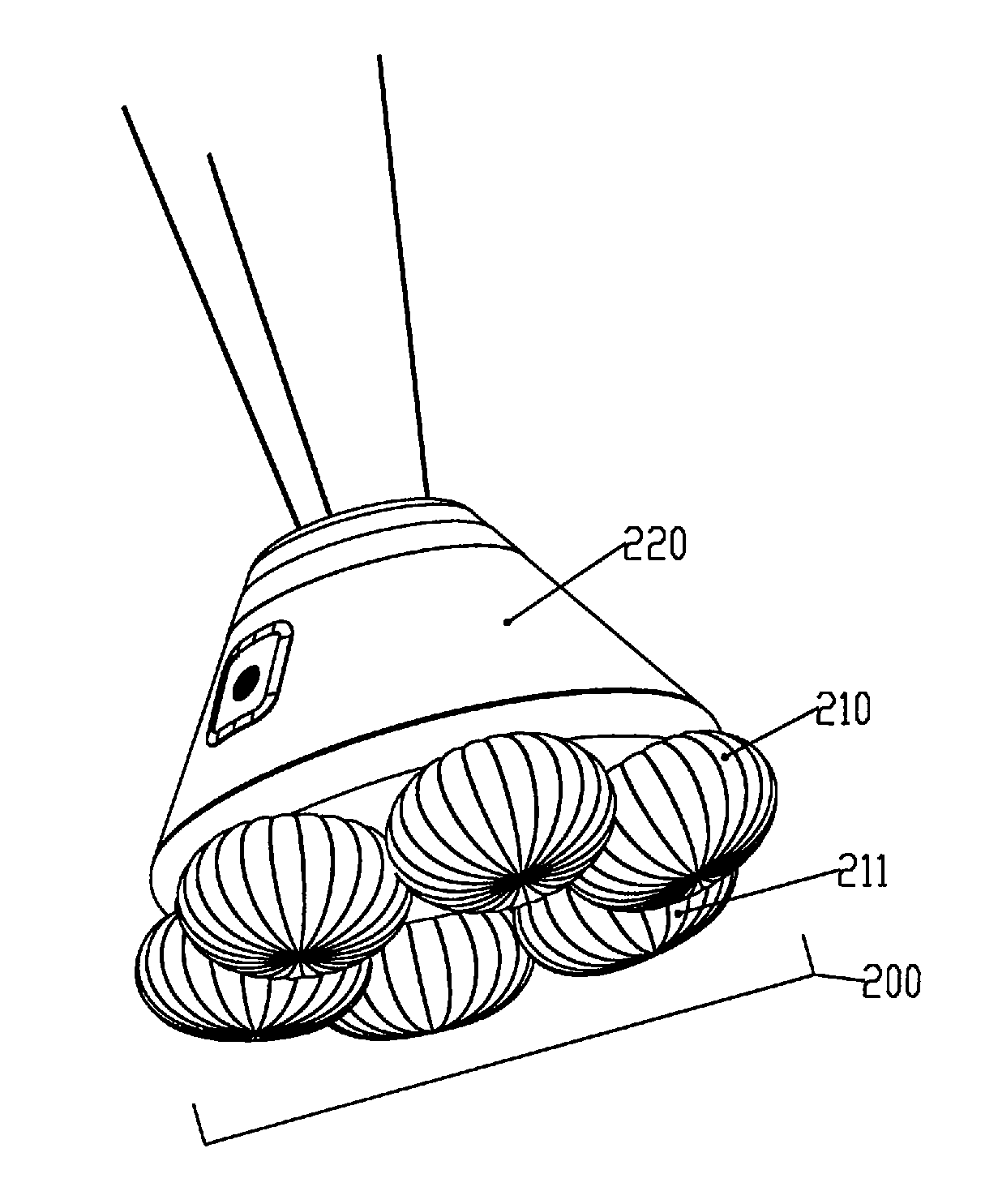
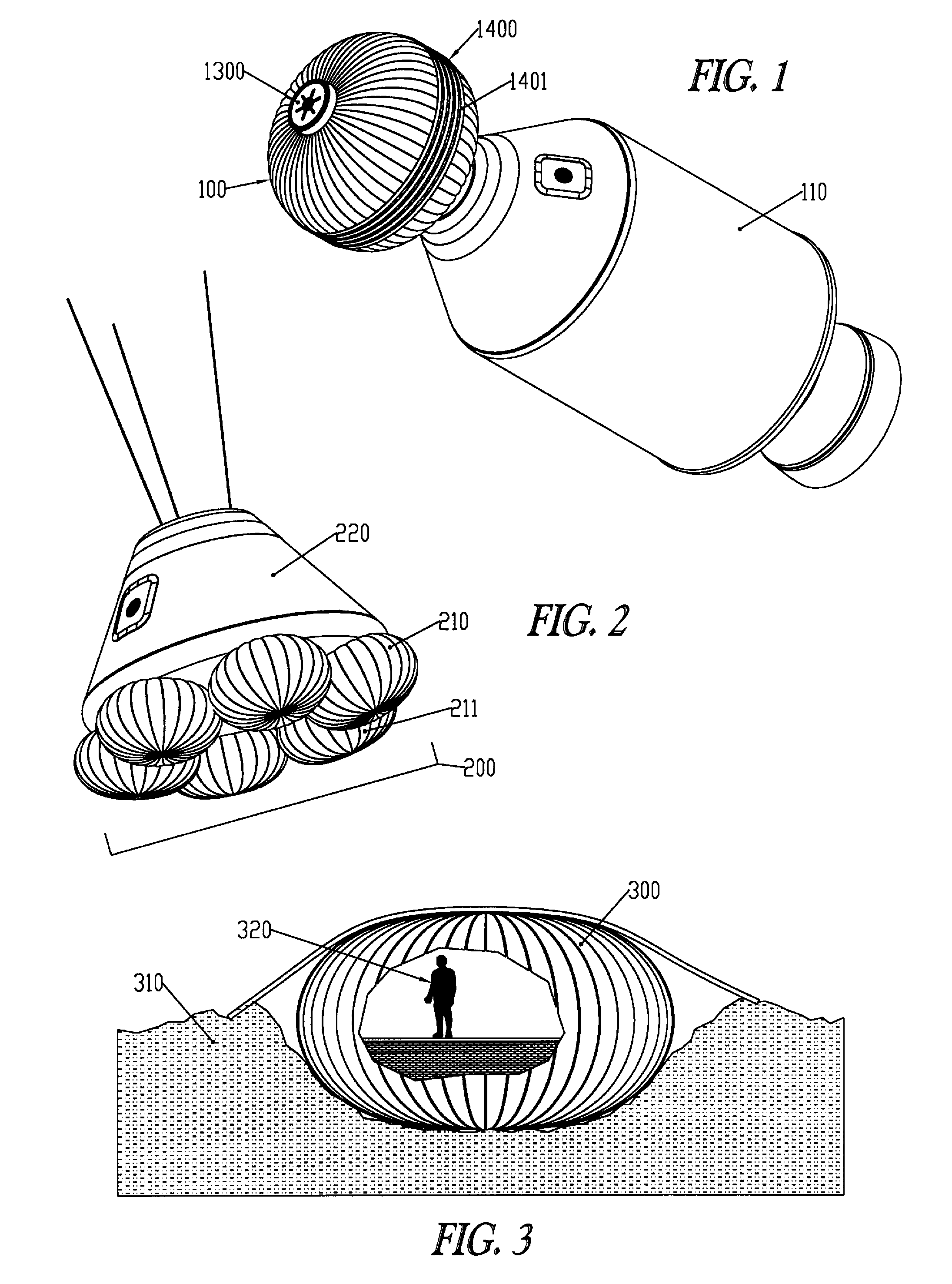
[0017]Sectioning the spheroid of the aforementioned example restraint embodiment at its equator and connecting each of the two resulting hemispheroidal end caps to the respective open ends of a cylinder provides an alternate, elongate example embodiment resembling a conventional pressure vessel and allowing additional configurational and dimensional flexibility. The cylinder's constant diameter is maintained by the addition of a circumferential component to the vessel's restraint which, depending on requirements, comprises fabric or parallel hoops of tendons or straps. Similarly, to create the characteristically tapered profile of a space capsule or re-entry ballute, the spheroid is sectioned on a parallel other than the equator and the resulting natural shape end caps are resized to fit the ends of a frustoconical center section. The natural shape is maintained as default geometry within the vessel's end caps regardless of the parallel partitioning of the spheroid of the invention's basic embodiment.
[0018]Each polar end structure of the vessel may be rigid or flexible depending on requirements. Without compromise in strength, the vessel can be manufactured as a fully functional embodiment without incorporation of any significant rigid components such as rigid end structures or internal core thereby further broadening the vessel's potential range of application, as well as having greater compressibility, lighter weight, greater robustness, and reduced cost.
[0020]Conversely, the vessel of the invention may incorporate a rigid end structure at one or both vessel poles or a mating structure such as a docking bay, air lock or the like, to which the vessel's tendons are structurally attached by common methods. If configurationally permitted, the present vessel's end structure may be prepared with a flexible end structure of adequately large aperture to allow its fitment to the mating structure. In general, the invention's flexible end structure embodiment allows great versatility and facilitates significant opportunity for the vessel's modular combination with, or integration into, other architecture.
[0021]The vessel of the present invention provides a barrier structure which is the vessel's substantially impervious barrier membrane for the containment of pressurized gaseous or liquid fluids interior to the membrane. The barrier structure comprises at least one high-modulus structural carrier layer confining one or more substantially impervious bladder layers. A connection system of sufficient strength to maintain its integrity throughout the vessel's operational parameters is provided to accurately index the barrier structure to the inside of the vessel's meridional array of restraint tendons and to allow modular assembly of the aforementioned components.
[0022]In an example embodiment, the invention provides for a method of manufacture for the barrier structure whereby two substantially planar circles of barrier structure material are sealingly connected to one another along their edges whereby the three dimensional natural shape is effectively derived from the pressurization of this simple two dimensional barrier structure. With the subsequent connection of a suitably dimensioned restraint structure to the barrier structure, excess barrier structure material presented upon the vessel's pressurization is restructured into an array of lobes bulging outwards between the members of the corresponding array of restraint tendons thereby facilitating the beneficial stress distribution described earlier. The resulting embodiment of the vessel of the present invention provides simple, modular vessel assembly.

Problems solved by technology

While low elongation is a great benefit for maintaining vessel geometry, it becomes an Achilles' heel if the vessel is not meticulously engineered: Due to their high modulus it is difficult to guarantee proper load sharing between individual fibers within a woven fiber product, thereby making any interface, joint, or seam the potential point load induced source of chain reaction failure.
This does not ultimately bode well for ‘broad’ fabrics since, the greater the width of the weave, the more difficult it becomes to precisely balance the load sharing between individual fibers.
The ultimate strength limitation which precludes use of fabric gore vessels in high load applications stems from the aforementioned inefficiency of fiber load sharing in broad fabrics combined with the necessity that individual meridional gores must be cut in a lens shape to allow for the assembly of the intended three dimensional pressure shell.
Unfortunately, broad fabric cross-seam strength loss is always substantial, often over 40% for high performance fabric woven of high modulus fiber.
Moreover, if higher membrane stresses require application of thicker fabric, the seam will carry a yet lower percentage of the base fabric strength due to the decreased load sharing precision amongst the greater number of fibers.
Multiple layers of fabric are sometimes used to avoid thick mono-layers, however load sharing between fabrics constructed of high modulus fiber becomes not only an immense integration challenge but a nightmare due to rampant manifestation of indeterminate load pathways.
A further limitation posed by heavier fabric structures is the increased seam sewing difficulty, most dramatically manifesting itself in the polar areas of meridional seam convergence and often the ultimate limiting factor in fabric gore structure design performance.
Finding a solution to the meridional bulk convergence problem is one of the great recurring challenges in flexible vessel design.
Hybrid design is based on the premise that materials providing the surface coverage and impermeability necessary for the containment of the vessel's fluid contents are not ideal for simultaneously bearing the vessel's global pressure and mass loads and vice versa.
The drawback of hybrid vessels is the fact that no convenient solution has been found to maintain circumferential tendon hoops correctly positioned on the vessel's steep end cap surfaces.
As evidenced above, a cornerstone challenge in flexible vessel design is the development of correspondingly flexible end caps.
This is significant because almost unwittingly a viable end cap is presented through simple, although perhaps counterintuitive, elimination of the entire circumferential portion of a hybrid vessel's restraint structure.
Firstly the capability of these vessels is limited to extremely thin, low pressure membranes, and secondly, there is no provision for a vessel specifically intended to present both collapsed and deployed configurational functionality.

Method used


Image

  • Flexible vessel
  • Flexible vessel
  • Flexible vessel

Examples


Embodiment Construction

[0045]In the following detailed description of the example embodiments, reference is made to the accompanying drawings that form a part hereof, and in which are shown by way of illustrating specific example embodiments. The example embodiments illustrated are described in sufficient detail to enable those skilled in the art to practice the teachings disclosed herein. Other example embodiments can be utilized and derived therefrom, such that structural and logical substitutions and changes can be made without departing from the scope of the claims. The following detailed description, therefore, is not to be taken in a limiting sense, and the scope of various embodiments is defined only by the appended claims, along with the full range of equivalents to which such claims are entitled.

[0046]The example embodiments described below are illustrative of the so-called ‘multidisciplinary technology’ common in space architecture where highly complex devices are required to perform with the ut...


PUM


Abstract

A flexible vessel includes a restraint structure and a barrier structure. The restraint structure further includes a first portion, and a second substantially rounded end cap portion that is attached to the first portion. The restraint structure also includes an array of tendons. The barrier structure is positioned within the restraint structure. When the barrier contains a fluid, a portion of the load is carried by the restraint structure and another portion of the load is carried by the barrier structure. The flexible vessel is collapsible to occupy a first volume and distended to occupy a second volume. The flexible vessel is part of a system when used in various applications with respect to a craft.

Description

FIELD OF THE INVENTION[0001]This invention relates generally to flexible vessels for the containment of gaseous or liquid fluids. More particularly, the invention is capable of high strength-to-weight ratio construction, of carrying high pressure induced stress, and may furthermore be collapsed to occupy a relatively small volume, and distended to retain a relatively large internal volume. As such, the invention is a particularly suitable pressure confining structure for incorporation into architecture deployed in outer space and on or about celestial bodies.BACKGROUND[0002]Specialized markets provide continuous impetus for the development of high performance pressure vessels. Performance is measured across a set of desirable attributes which differ in priority depending on the vessel's intended application. Two commonly identified primary performance attributes are robustness and high strength-to-weight ratio. Vessels engineered for operation in environments of lower pressure than ...

Claims


Application Information

Patent Timeline
Patent Type & Authority Applications(United States)
IPC IPC(8): B64G1/00B64G99/00
CPCB64D2201/00B64G1/222B64G2001/224B64G1/646B64G9/00B64G1/62B64G99/00B64G1/2227
Inventor DE JONG, MAXIM
Owner THIN RED LINE AEROSPACE
Why Eureka
Try Eureka