Cell operation methods using gate-injection for floating gate nand flash memory

Active Publication Date: 2008-04-03
MACRONIX INT CO LTD
View PDF20 Cites 218 Cited by
  • Summary
  • Abstract
  • Description
  • Claims
  • Application Information

AI Technical Summary

Benefits of technology

[0008]Devices having a bulk-tied FinFET-like structure are particularly suited to this method, as the structure creates a naturally low gate coupling ra

Problems solved by technology

This result is satisfactory for larger memory devices, but when these devices are scaled down, a high GCR becomes difficult to maintain.
The bottom tunnel oxide will not have a sufficiently large electric field to allow FN tunneling.
Additionally, there is a problem of i

Method used


Image

  • Cell operation methods using gate-injection for floating gate nand flash memory
  • Cell operation methods using gate-injection for floating gate nand flash memory
  • Cell operation methods using gate-injection for floating gate nand flash memory

Examples


Embodiment Construction

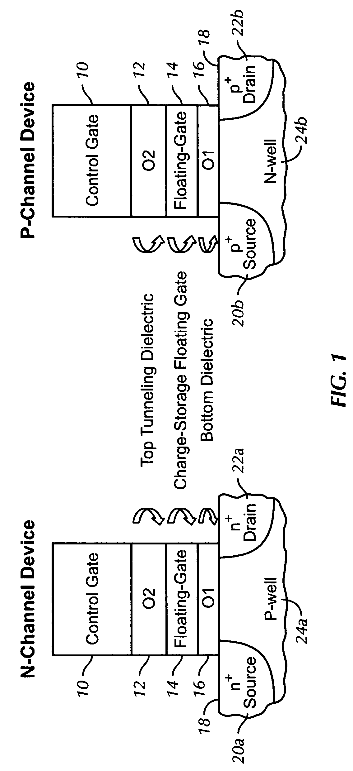
[0017]FIG. 1 shows typical cross-sectional views in the channel length direction of flash memory cells for use in embodiments of the present invention. The left diagram of FIG. 1 shows an n-Channel device. The structure contains a Si channel 18, with a p-well 24a and n-doped source 20a and drain 22a. In preferred embodiments, a bulk-tied FinFET structure is used. The structure also contains a gate oxide 16, a charge-storage floating gate 14, an inter-poly, top-tunneling dielectric 12, and a control gate 10. The right side of FIG. 1 shows a p-Channel device, which is identical to the n-Channel device, except that the Si channel 18 contains an n-well 24b, and p-doped source 20b and drain 22b.

[0018]The bottom gate oxide 16 is under relatively small electric field stress, typically less than about 7 MV / cm, during program and erase operations. This avoids any FN tunneling, which prevents much of the damage occurring in conventional flash memory devices, and allows a better DC performanc...


PUM


Abstract

A method of performing an operation on a flash memory cell device, used when a gate coupling ratio between a floating gate and a control gate of less than 0.4. A potential is required to be applied across the control gate. Electrons are either injected to the floating gate from the control gate or ejected from the floating gate to the control gate. The operation associated with the injection or the ejection is determined by the nature of a silicon channel provided in the device. Devices using a bulk-tied FinFET-like structure are particularly suited to this method. The method is also particularly suited for use on cells in a NAND array.

Description

BACKGROUND OF THE INVENTION[0001]The use of floating gate technology in flash memory devices is well known. Typically, a Si channel of n or p type semiconductor is provided. The floating gate transistor is surrounded by oxide, enabling a charge stored on the gate to remain there. Program and erase operations take place by a process of channel injection. Electrons undergo Fowler-Nordheim (FN) tunneling and are transferred from the channel to the floating gate, and vice-versa, during operation.[0002]To provide an efficient channel injection, the possibility of a gate injection (transfer of electrons between the control gate and floating gate via FN tunneling) must be reduced. This is accomplished by maximizing the gate coupling ratio. The gate coupling ratio (GCR) is defined as the ratio of floating gate potential to control gate potential. A GCR of 1 is optimal, but a GCR greater than 0.6 is sufficient for most flash memory devices.[0003]This result is satisfactory for larger memory ...

Claims


Application Information

Patent Timeline
IPC IPC(8): G11C16/04G11C11/34H01L29/76
CPCG11C16/0416G11C16/10H01L21/28273H01L29/7883H01L29/66795H01L29/66825H01L29/7851H01L27/115H01L29/40114H10B69/00H10B41/35
Inventor LUE, HANG-TINGHSU, TZU-HSUANLAI, ERH-KUN
Owner MACRONIX INT CO LTD
Why Eureka
Try Eureka