
Sensor unit of thermal analysis equipment and method of manufacturing the same

a technology of thermal analysis equipment and sensor unit, which is applied in the direction of instruments, heat measurement, material heat development, etc., can solve the problems of insufficient thermal resistance between the measurement sample and the reference sample, the temperature change in the sample cannot be detected with high sensitivity, and the sensor sensitivity is not formed, so as to achieve high sensitivity, increase the thermal electromotive force, and improve the sensitivity and s/n ratio of the sensor

Inactive Publication Date: 2008-04-03
RIGAKU CORP
View PDF11 Cites 27 Cited by
  • Summary
  • Abstract
  • Description
  • Claims
  • Application Information

AI Technical Summary

Benefits of technology

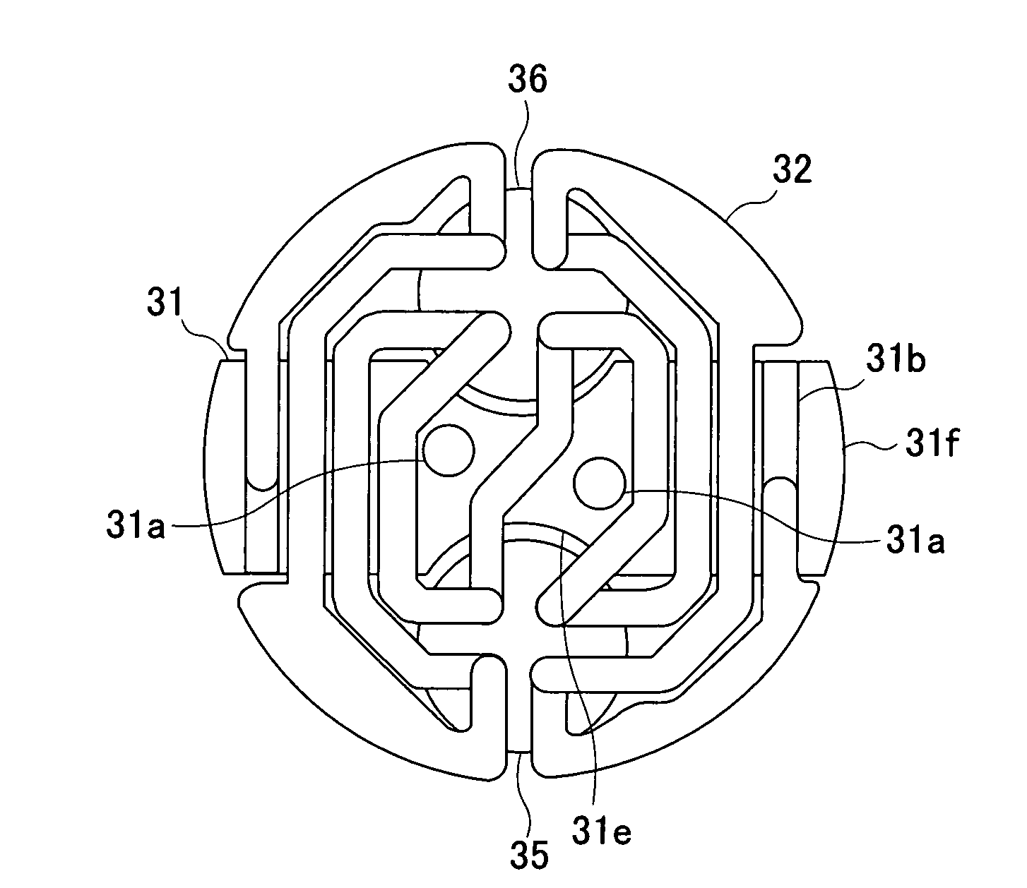
[0011]In this way, in the sensor unit of thermal analysis equipment of the present invention, the heat sensitive parts are provided spaced apart from the base part. Therefore, an appropriate thermal resistance is provided between the heat sensitive parts and the base part. Accordingly, if there is a change in the measurement sample, a steep temperature gradient will occur between the measurement sample and the reference sample and the thermal electromotive force will increase. As a result, the sensitivity and S / N ratio of the sensor will improve. Moreover, a temperature change in the sample can be detected with high sensitivity by preventing the heat transmitting to the heat sensitive part.
[0028]On the other hand, the multiple thermocouple can transmit heat from the base part to each heat sensitive part, and the time constant of sample temperature can be kept small. As a result, a change in the heat absorption and heat generation, and the like of the measurement sample can be detected satisfactorily.

Problems solved by technology

However, in the above-described sensor, the sample containers are just placed at positions apart from each other on the insulating layer, and therefore a sufficient thermal resistance is not formed between the measurement sample and the reference sample.
For this reason, even if there is a change in the measurement sample, a sufficient temperature gradient will not occur between the samples, thus decreasing the sensor sensitivity.
Since an insufficient thermal resistance affects the measurement sensitivity in this manner, a temperature change in the sample can not be detected with high sensitivity in such thermal analysis equipment as described above.

Method used


Image

  • Sensor unit of thermal analysis equipment and method of manufacturing the same
  • Sensor unit of thermal analysis equipment and method of manufacturing the same
  • Sensor unit of thermal analysis equipment and method of manufacturing the same

Examples


Embodiment Construction

Best Modes for Carrying Out the Invention

[0035]Next, an embodiment of the present invention will be described with reference to the accompanying drawings. For ease of understanding of the description, in each drawing the same reference numeral is given to the same component, and the duplicating description is omitted.

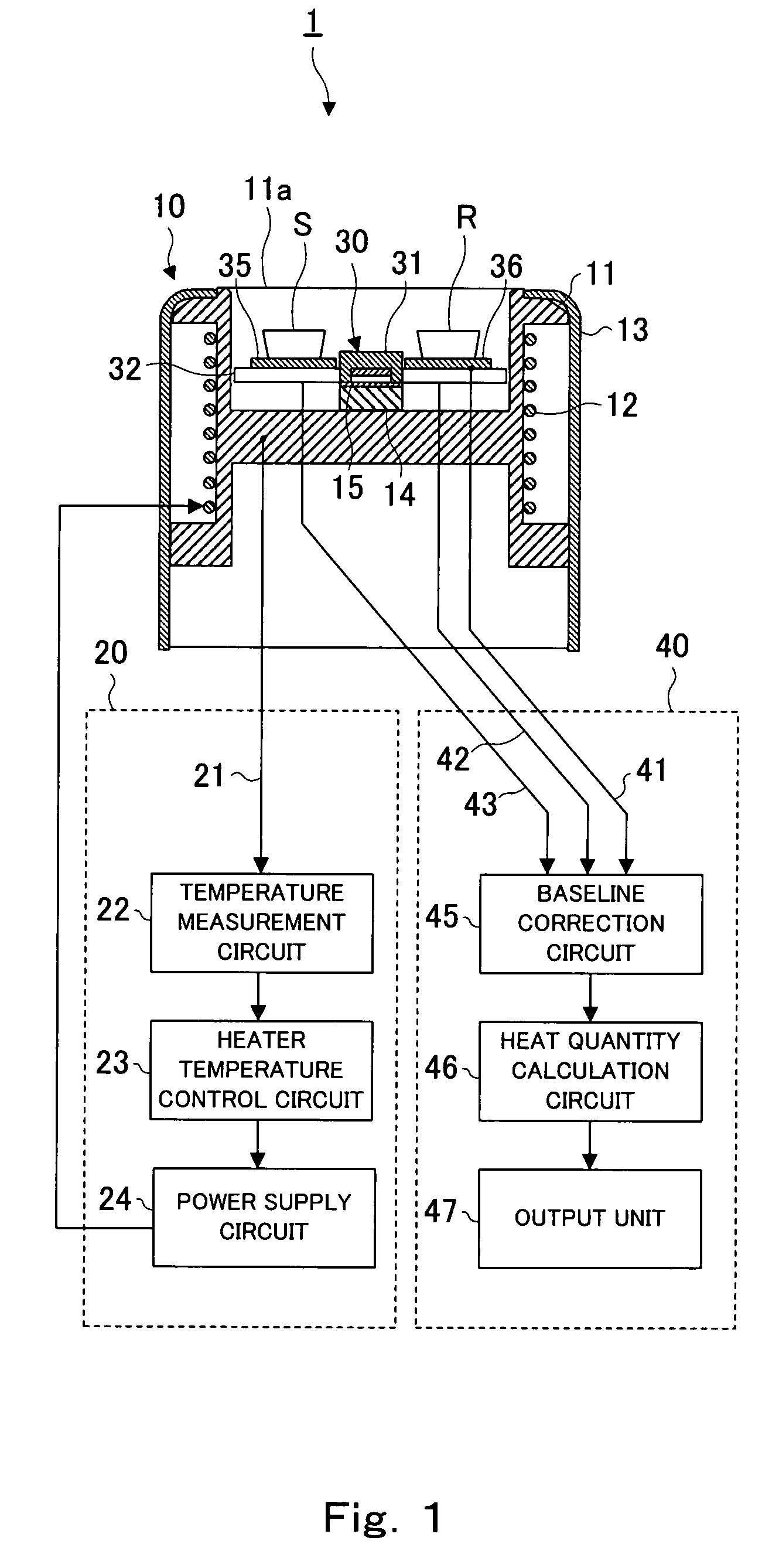
[0036]FIG. 1 is a cross sectional view schematically showing a thermal analysis equipment 1. The thermal analysis equipment 1 is the so-called heat flux DSC that detects a temperature difference between a measurement sample S and a reference sample R by controlling the temperature of a furnace unit 10, and outputs a heat flow difference. Other than this, the thermal analysis equipment 1 can be used also as a DTA that simply detects a temperature difference.

[0037]As shown in FIG. 1, the thermal analysis equipment 1 mainly includes the furnace unit 10, a furnace body temperature control circuit 20, a sensor unit 30, and an output circuit 40. The furnace unit 10 further ha...


PUM

PropertyMeasurementUnit
temperatureaaaaaaaaaa
heat sensitiveaaaaaaaaaa
widthaaaaaaaaaa

Abstract

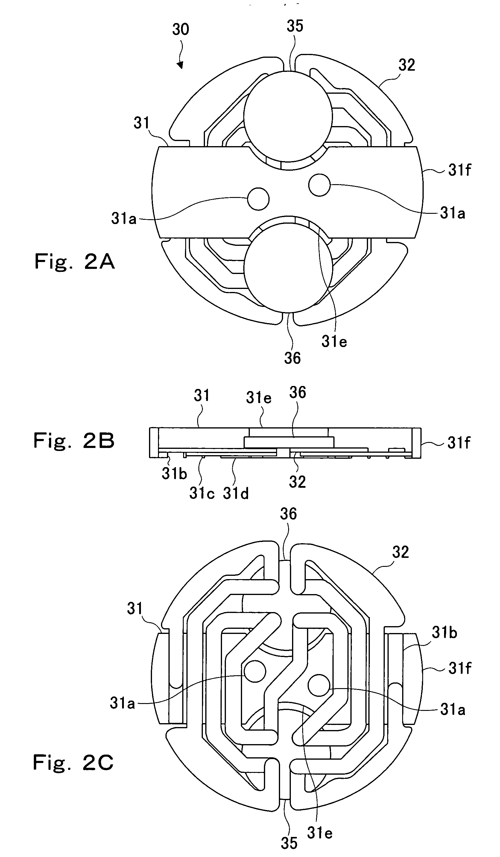
There are provided a sensor unit of thermal analysis equipment capable of keeping heat conduction between a furnace body and samples to detect a temperature difference between the samples with high sensitivity, while suppressing the heat conduction between a measurement sample and a reference sample, and a method of manufacturing the same. According to the present invention, a sensor unit 30 of a thermal analysis equipment 1 that detects a temperature difference between a measurement sample S and a reference sample R in each sample container, includes: a base part 31 formed of an insulator and provided in the vicinity of a temperature-controlled furnace unit; a multiple thermocouple 32 formed by joining two kinds of thermocouple elements alternately, a particular part of the thermocouple element being joined to the base part; and a pair of heat sensitive parts 35, 36 formed of an insulator, having a mounting surface on which each sample container is mounted, and joining to element junctions of the multiple thermocouple, wherein the pair of heat sensitive parts 35, 36 are provided spaced apart from the base part 31.

Description

BACKGROUND OF THE INVENTION[0001]1. Field of the Invention[0002]The present invention relates to a sensor unit of thermal analysis equipment for detecting a temperature difference between a measurement sample and a reference sample, and a method of manufacturing the same.[0003]2. Description of the Related Art[0004]Conventionally, a temperature difference sensor with a pair of thermocouples is generally used in thermal analysis equipment, such as DTA (Differential Thermal Analyzer) and DSC (Differential Scanning Calorimeter). Such a temperature difference sensor detects the temperature of a measurement sample and the temperature of a reference sample by means of each thermocouple, respectively, and outputs the temperature difference. In thermal analysis equipment, a metal such as constantan, which is excellent in thermal conductivity and will not react with thermocouple materials even at high temperatures, is usually used for each mounting plate for mounting a sample container, and ...

Claims


Application Information

Patent Timeline
Patent Type & Authority Applications(United States)
IPC IPC(8): G01K7/02
CPCG01K7/02Y10T29/49002G01N25/48G01K17/006
Inventor TANAKA, NOBUHIROOTAKE, SATOSHITAKATA, YOSHIHIRO
Owner RIGAKU CORP
Learn More