Method and apparatus for improving the distribution of compressive stress

Inactive Publication Date: 2008-04-03
PREVEY PAUL S +1
View PDF11 Cites 17 Cited by
  • Summary
  • Abstract
  • Description
  • Claims
  • Application Information

AI Technical Summary

Benefits of technology

[0024]In another preferred embodiment of the invention, the method and apparatus of this invention may be applied using small portable tools to components, such as aircraft engine or st

Problems solved by technology

The relatively small size and high velocity of the shot cause significant lateral displacement and plastic deformation at the surface of the article, thereby producing a highly compressive surface layer of residual stress at the expense of depth and magnitude of subsurface compression.
The depth of the subsurface compressive stress is limited due to the size of the impacted shot.
Further, the use of randomly impacted shot to achieve uniform surface coverage causes a high occurrence of areas subject to multiple impacts.
The redundant impacts result in a highly cold worked surface that may be undesirable if thermally stable compressive residual stresses are desired.
The repeated impacts of shot on the surface during the shot peening process can cause surface damage in the form of laps and folds that act as stress concentrations that serve an fatigue crack initiation sites, reducing fatigue strength.
In some applications, residue from the peening media (usually steel, glass or ceramic sh

Method used


Image

  • Method and apparatus for improving the distribution of compressive stress
  • Method and apparatus for improving the distribution of compressive stress
  • Method and apparatus for improving the distribution of compressive stress

Examples


Embodiment Construction

[0033]The present invention addresses the limitations of currently available surface treatment methods by providing an apparatus and method for producing an article having at least one metallic portion with a continuous, deep layer of high magnitude compressive residual stress that extends from the surface to a depth beneath the surface of at least one of the portion(s).

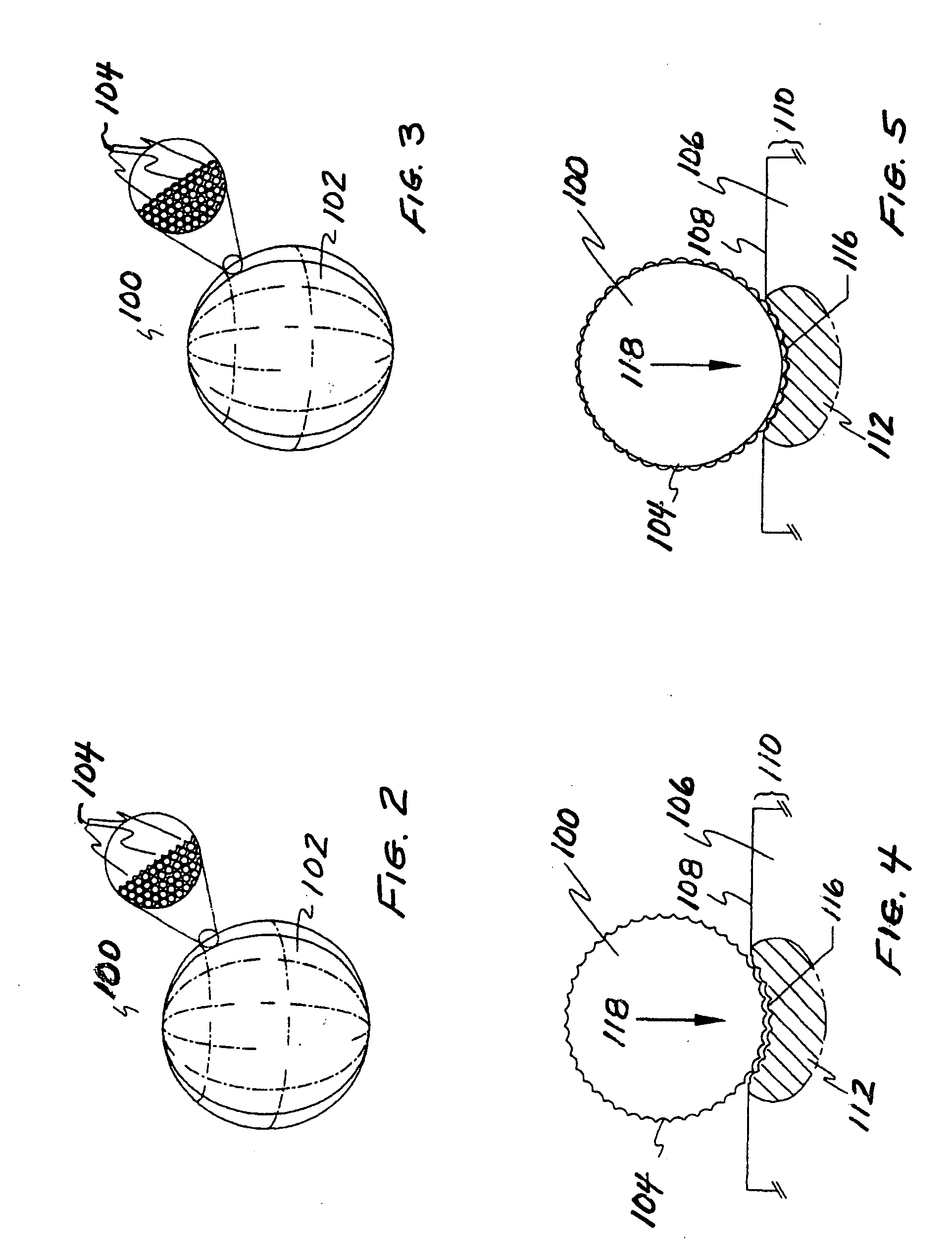
[0034]Referring to FIG. 2, the apparatus for improving the distribution of compressive stress is a surface treatment element 100 for use in conjunction with hydrostatic, ball-type burnishing tools, wheel or roller burnishing tools, indenting tools and impact / pinch peening tools. By way of example, the surface treatment element 100 shown in FIGS. 2 and 3 is a spherical element for use in conjunction with a conventional hydrostatic, ball-type burnishing tool. Alternatively, the surface treatment element may have a variety of forms including cylindrical, hemispherical, conical, or disk-shaped depending on the particular...


PUM

PropertyMeasurementUnit
Diameteraaaaaaaaaa
Surfaceaaaaaaaaaa
Deformation enthalpyaaaaaaaaaa

Abstract

A surface treatment element having a textured surface with a plurality of deforming features is pressed against the surface of an article to induce deep and shallow layers of compressive residual stress to form a continuous layer of compressive residual stress extending from the surface to a depth beneath the surface. A method whereby a surface treatment apparatus is pressed into the surface of the apparatus to cause Hertzian loading thereby inducing a deep, high magnitude compressive residual stress below the surface. The deforming features of the surface treatment element cause the lateral displacement of material on the surface of the article thereby cold working the surface and providing a more shallow layer of compressive residual stress at the surface.

Description

[0001]This application claims the benefit of U.S. Provisional Patent Application No. 60 / 848,076, filed Sep. 29, 2006.BACKGROUND OF THE INVENTION [0002]The present invention relates to an apparatus and method for introducing an improved compressive residual stress distribution along at least a portion of the surface and to a depth below at least a portion of the surface of an article to improve resistance to stress related failure mechanisms and, more particularly, to a surface treatment apparatus with a textured contact surface for introducing a highly compressive layer along at least a portion of the surface and to a depth below at least a portion of the surface of an article.[0003]The introduction of compressive residual stresses along and below the surface of an article is known to improve the fatigue and stress corrosion cracking performance of the article. A variety of different methods are used to introduce compressive residual stresses including shot peening, glass bead peeni...

Claims


Application Information

Patent Timeline
IPC IPC(8): B32B33/00C21D7/04
CPCY10T428/12458C21D7/06
Inventor PREVEY, PAUL S.HAAS, JOHN E.
Owner PREVEY PAUL S
Why Eureka
Try Eureka