Stent Graft Delivery System for Accurate Deployment

Inactive Publication Date: 2008-04-03
VASCULAR INNOVATIONS
View PDF99 Cites 155 Cited by
  • Summary
  • Abstract
  • Description
  • Claims
  • Application Information

AI Technical Summary

Benefits of technology

[0008] This invention relates to a stent graft delivery device. The present invention facilitates accurate positioning of a stent or stent graft at a desired lesion site while preventing or limiting undesirable stent or stent graf

Problems solved by technology

With many conventional catheters, implant movement during deployment may occur from frictional interference or contact with the catheter sheath as the catheter sheath is retracted from about the implant.
Moreover, covering undesired locations, such as healthy vessels and/or branch vessels, due to inaccurate implant placement may cause unfavorable clinical consequences, such as branch vessel occlusion and/or restenosis.
Such migration may result in inaccurate positioning of the stent graft with respect to the lesion site.
Further, in abdominal aneurysm procedures, an inadequate distance between an edge of the renal artery and an edge of the aneurysm, commonly referred to as a “short neck,” may prevent or limit a patient's acceptance of an endovascular treatment or procedure.
Such element overlap in these stent grafts may

Method used


Image

  • Stent Graft Delivery System for Accurate Deployment
  • Stent Graft Delivery System for Accurate Deployment
  • Stent Graft Delivery System for Accurate Deployment

Examples


Embodiment Construction

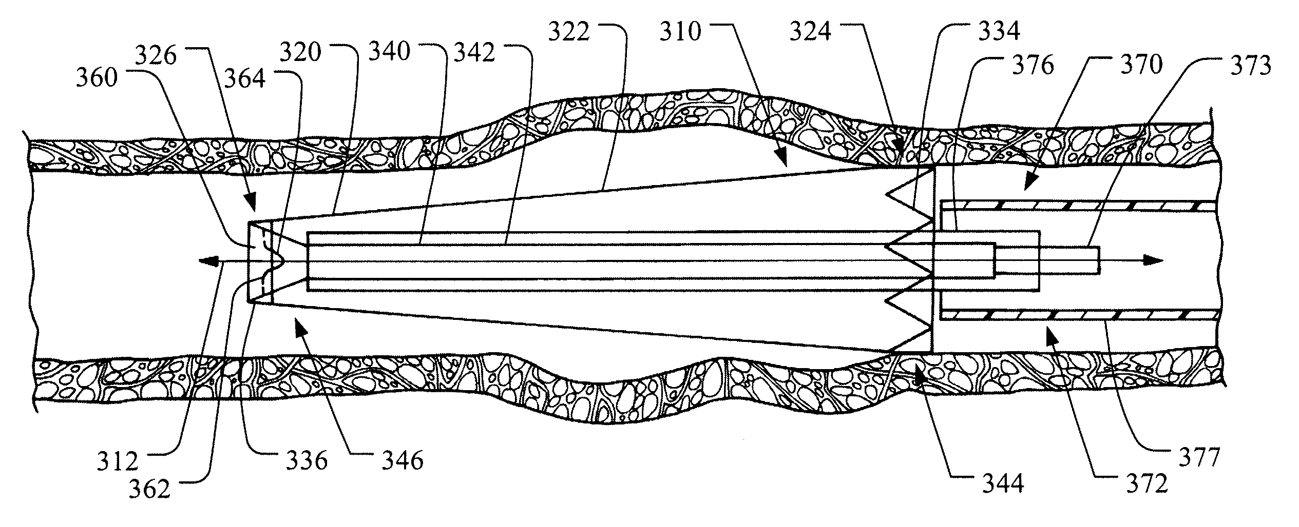
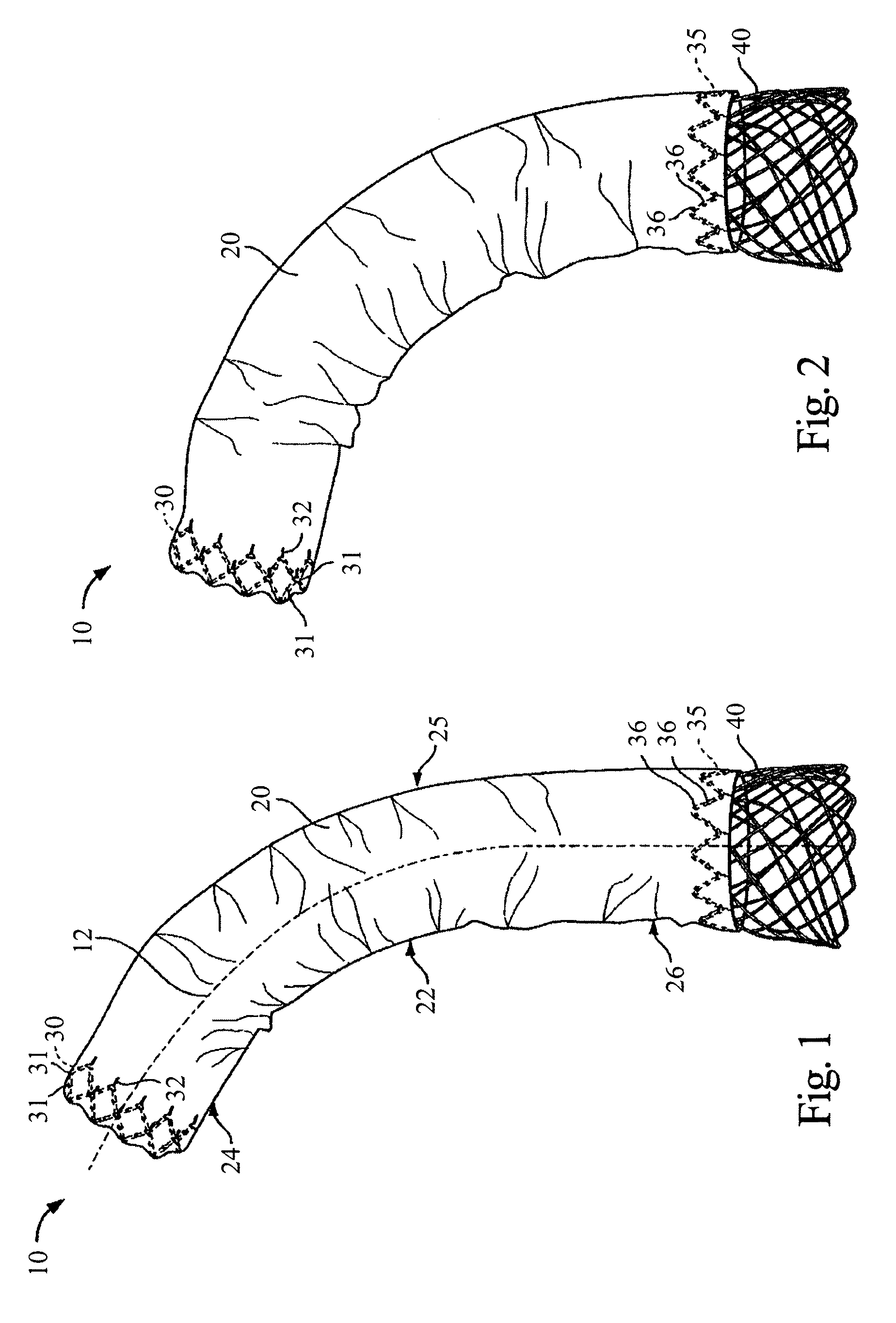
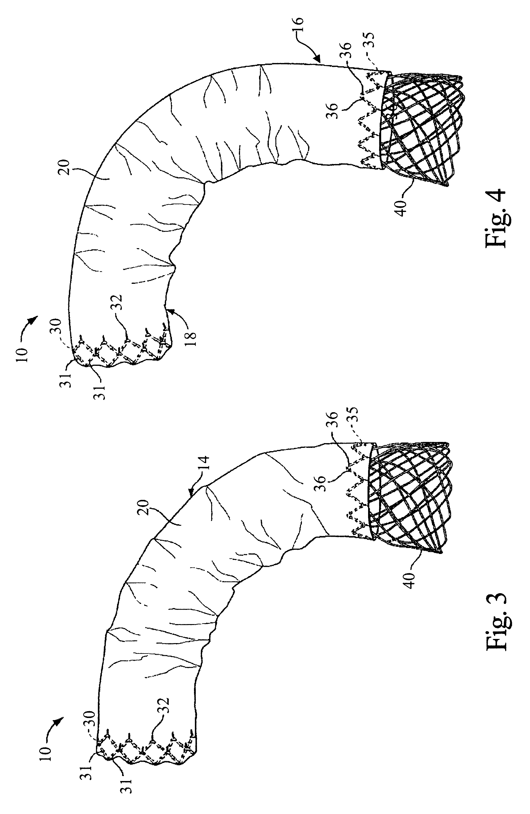
[0132] The present invention provides a delivery system for deploying a stent graft in a body vessel, for example for repairing and / or treating aneurysms such as abdominal aortic and thoracic aortic aneurysms. The stent and stent graft may have a configuration that, upon deployment, adapts or conforms to the body vessel. More specifically, with the stent or stent graft positioned at a lesion site within a curved portion of a blood vessel, the stent or stent graft is adaptable to the anatomical curvature of the blood vessel.

[0133] The present invention facilitates accurate positioning of the stent or stent graft at the desired lesion site while preventing or limiting undesirable stent or stent graft movement and / or migration. Further, a post-deployment placement of the stent or stent graft with respect to the lesion site can be accurately predicted or determined to prevent undesirable blockage or occlusion of branch vessels.

[0134] The stent graft may be deployed from a distal end (...


PUM


Abstract

A delivery system for deploying a stent graft at a lesion site is provided. The delivery system comprises a wire lumen and a support stent slidably positioned about the wire lumen. The support stent is expandable from a compressed delivery configuration to an expanded configuration. An inner sheath is retractably positioned about the support stent with the support stent in the delivery configuration. An anchor stent is slidably positioned about the inner sheath. A tubular graft proximal end is coupled to the anchor stent and deployable with the anchor stent from a compressed delivery configuration to a deployed configuration. An outer sheath is retractably positioned about the anchor stent and the graft in the compressed delivery configuration.

Description

RELATED APPLICATIONS [0001] This application claims the benefit of: 1) provisional U.S. Patent Application Ser. No. 60 / 848,197, filed Sep. 28, 2006; 2) provisional U.S. Patent Application Ser. No. 60 / 848,198, filed Sep. 28, 2006; 3) provisional U.S. Patent Application Ser. No. 60 / 848,232, filed Sep. 28, 2006; and 4) provisional U.S. Patent Application Ser. No. 60 / 848,246, filed Sep. 28, 2006, all of which are incorporated herein by reference in their entirety.BACKGROUND OF THE INVENTION [0002] Expandable endovascular prosthetic implants, such as stents and stent grafts, can be loaded into a catheter for delivery and deployment at a lesion site, such as an aneurysm or dissection within a patient's vascular system. The catheter is typically configured to retain the prosthetic implant in a delivery configuration during delivery to the lesion site. At the lesion site, the prosthetic implant may be deployed, for example by retracting a catheter sheath from the prosthetic implant's proxim...

Claims


Application Information

Patent Timeline
IPC IPC(8): A61F2/06A61F2/90
CPCA61F2/07A61F2/90A61F2/95A61F2/89A61F2002/9511A61F2002/9517A61F2002/9665A61F2002/075A61F2/9517
Inventor TSENG, DAVID YILLORT, FRANCISCO MOISEF
Owner VASCULAR INNOVATIONS
Why Eureka
Try Eureka