Method for Deployment of a Stent Graft

a stent and graft technology, applied in the field of stent graft deployment, can solve the problems of inaccurate positioning of the stent graft with respect, preventing or restricting the acceptance of endovascular treatment or procedure, unfavorable clinical consequences, etc., to prevent or limit undesirable stent or stent graft movement and/or migration, accurate prediction or determination, and accurate positioning of the sten

Inactive Publication Date: 2008-04-03
VASCULAR INNOVATIONS
View PDF99 Cites 64 Cited by
  • Summary
  • Abstract
  • Description
  • Claims
  • Application Information

AI Technical Summary

Benefits of technology

[0008] The present invention relates to a method for accurate positioning of the stent or stent graft at the desired lesion site while preventing or limiting undesirable stent or stent graft movement and / or migration. Further, a post-deployment placement of the stent or stent graft with respect to the lesion site can be accurately predicted or determined to prevent undesirable blockage or occlusion of branch vessels.

Problems solved by technology

With many conventional catheters, implant movement during deployment may occur from frictional interference or contact with the catheter sheath as the catheter sheath is retracted from about the implant.
Moreover, covering undesired locations, such as healthy vessels and / or branch vessels, due to inaccurate implant placement may cause unfavorable clinical consequences, such as branch vessel occlusion and / or restenosis.
Such migration may result in inaccurate positioning of the stent graft with respect to the lesion site.
Further, in abdominal aneurysm procedures, an inadequate distance between an edge of the renal artery and an edge of the aneurysm, commonly referred to as a “short neck,” may prevent or limit a patient's acceptance of an endovascular treatment or procedure.
Such element overlap in these stent grafts may result in angular deformity of the stent graft and / or an increased potential for structural damage to the stent graft and / or the blood vessel from repetitive pulsatile motion induced by blood flow and / or pressure variations.
Additionally, kinking or bending of a stent graft placed in a curved vessel may occur, which may compromise the blood flow through the stent graft.
Attempts to provide stent grafts that are bent or otherwise curved to approximate the curvature of the blood vessel also may separate from the vessel wall because such stent grafts do not smoothly accommodate the curved vessel portion.
This separation may lead to an attachment endoleak, a flap occlusion and / or portions of the stent graft projecting into the graft component of the stent graft and / or into the blood vessel wall, causing damage and / or injury.

Method used


Image

  • Method for Deployment of a Stent Graft
  • Method for Deployment of a Stent Graft
  • Method for Deployment of a Stent Graft

Examples


Embodiment Construction

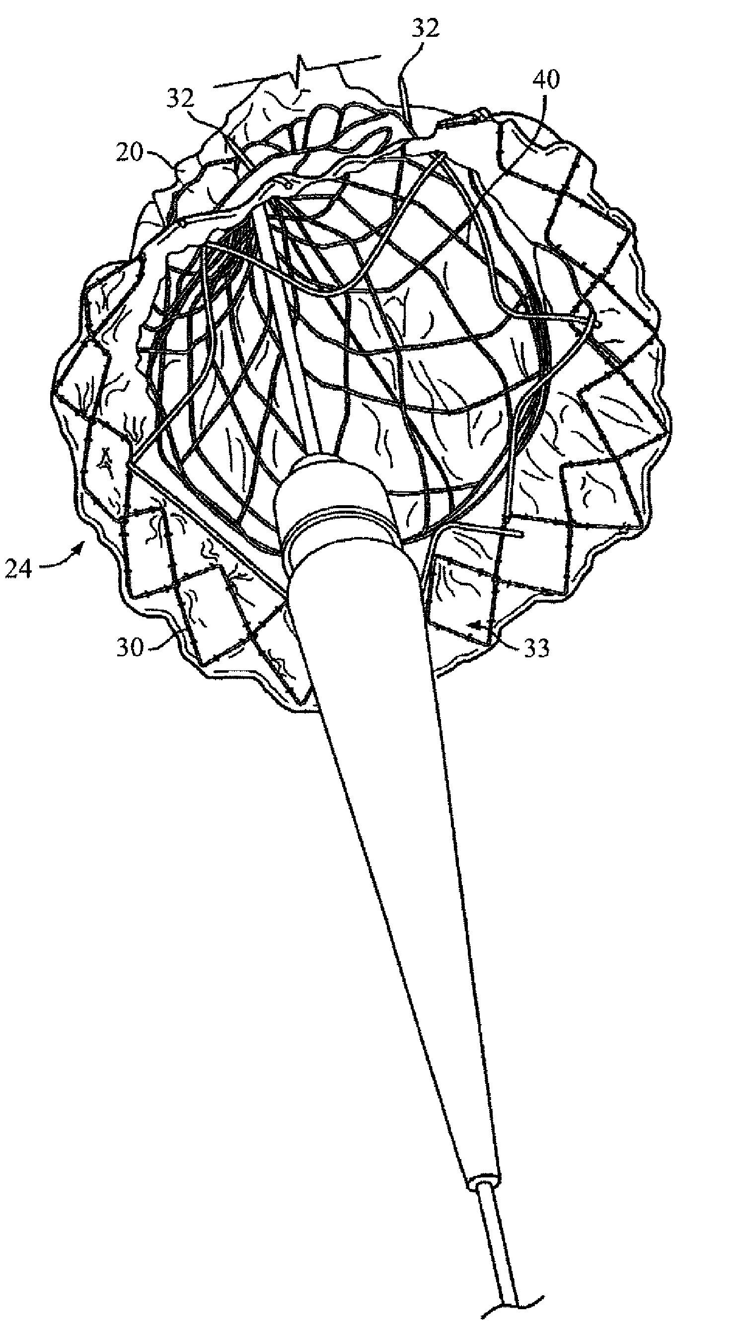
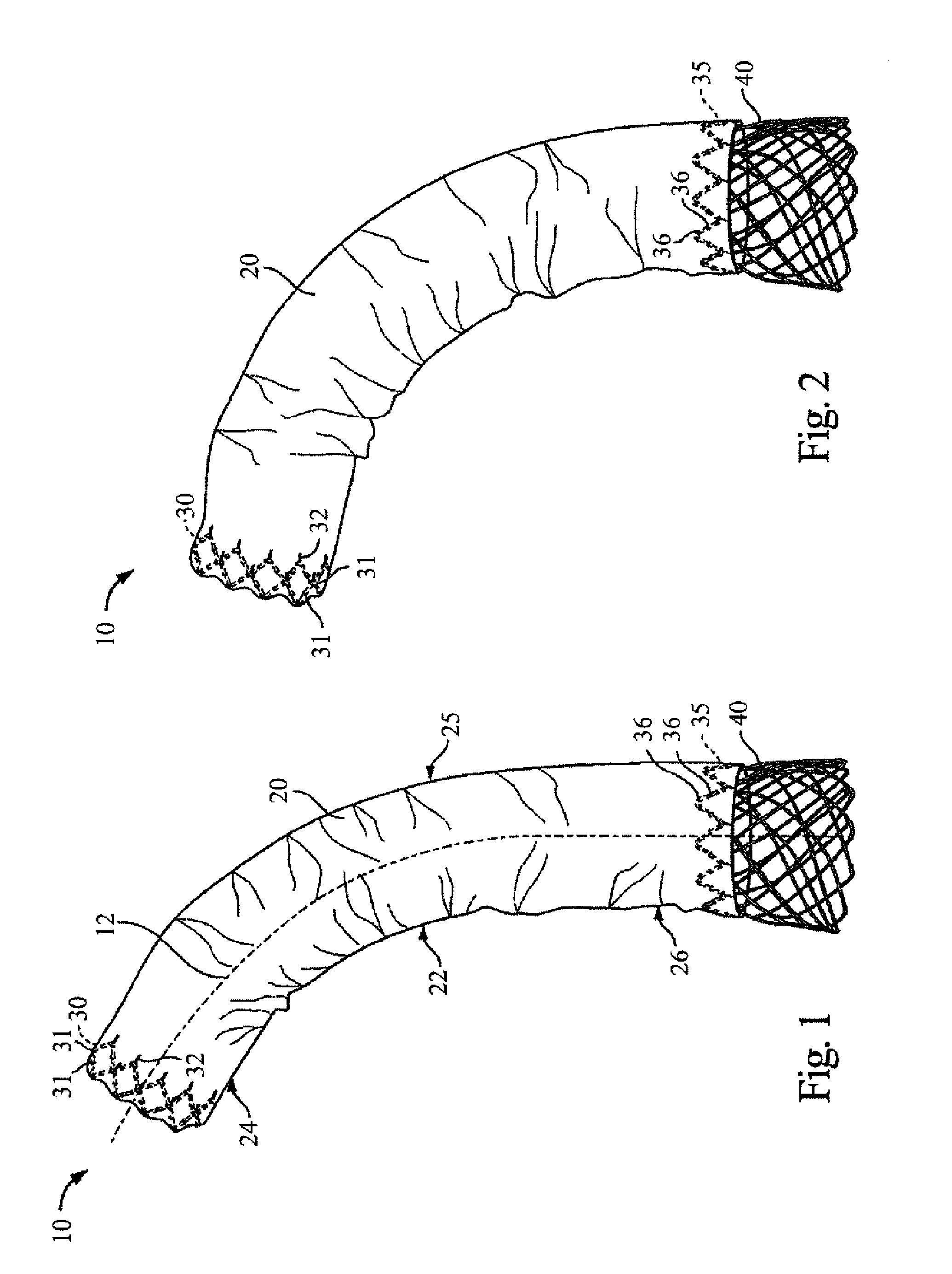
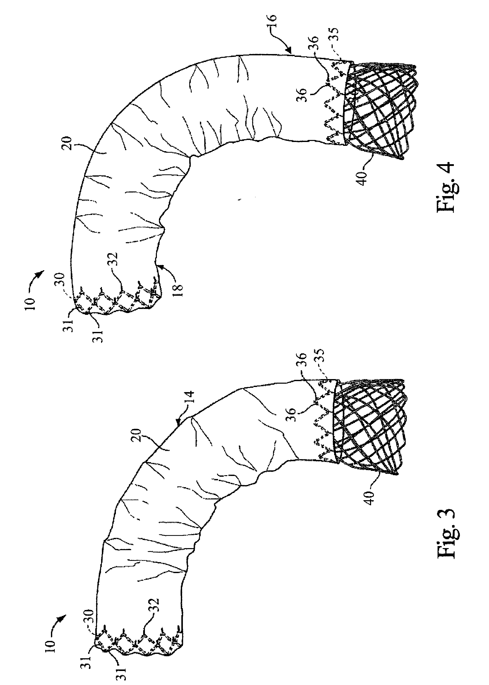
[0131] The present invention provides a method for repairing and / or treating aneurysms, such as abdominal aortic and thoracic aortic aneurysms. The method facilitates accurate positioning of the stent or stent graft at the desired lesion site while preventing or limiting undesirable stent or stent graft movement and / or migration. Further, a post-deployment placement of the stent or stent graft with respect to the lesion site can be accurately predicted or determined to prevent undesirable blockage or occlusion of branch vessels.

[0132] The stent graft may be deployed from a distal end (related to a position of a patient's heart) to the proximal end of the stent graft. The distal end is commonly referred to as the “bottom” position and the proximal end is commonly referred to as the “up” position. By deploying the stent graft in a “bottom-up” procedure, a distal end of the stent graft is precisely and accurately positioned at the desired lesion site and a post-deployment placement of...


PUM


Abstract

The method includes providing a delivery device. The delivery device comprises a support stent, an inner sheath, and an outer sheath. The support stent is slidably positioned about a wire lumen. The support stent has a proximal end and a distal end, and is expandable from a compressed delivery configuration to an expanded configuration. The inner sheath is retractably positioned about the support stent with the support stent in the delivery configuration. The anchor stent is slidably positioned about the inner sheath and is deployable from a compressed delivery configuration to a deployed configuration. The outer sheath is retracted to expand the anchor stent from the delivery configuration to an expanded configuration. The anchor stent is deployed in the body vessel. The inner sheath is retracted to expand the support stent from the compressed insertion configuration to an expanded configuration.

Description

RELATED APPLICATIONS [0001] This application claims the benefit of: 1) provisional U.S. Patent Application Ser. No. 60 / 848,197, filed Sep. 28, 2006; 2) provisional U.S. Patent Application Ser. No. 60 / 848,198, filed Sep. 28, 2006; 3) provisional U.S. Patent Application Ser. No. 60 / 848,232, filed Sep. 28, 2006; and 4) provisional U.S. Patent Application Ser. No. 60 / 848,246, filed Sep. 28, 2006, all of which are incorporated herein by reference in their entirety.BACKGROUND OF THE INVENTION [0002] Expandable endovascular prosthetic implants, such as stents and stent grafts, can be loaded into a catheter for delivery and deployment at a lesion site, such as an aneurysm or dissection within a patient's vascular system. The catheter is typically configured to retain the prosthetic implant in a delivery configuration during delivery to the lesion site. At the lesion site, the prosthetic implant may be deployed, for example by retracting a catheter sheath from the prosthetic implant's proxim...

Claims


Application Information

Patent Timeline
Patent Type & Authority Applications(United States)
IPC IPC(8): A61F2/06A61F2/90
CPCA61F2/07A61F2/90A61F2/95A61F2/89A61F2002/9511A61F2002/9517A61F2002/9665A61F2002/075A61F2/9517
Inventor TSENG, DAVID YILLORT, FRANCISCO MOISES
Owner VASCULAR INNOVATIONS
Why Eureka
Try Eureka