
Inflatable toroidal-shaped balloons

Active Publication Date: 2008-04-10
WL GORE & ASSOC INC
View PDF106 Cites 48 Cited by
  • Summary
  • Abstract
  • Description
  • Claims
  • Application Information

AI Technical Summary

Benefits of technology

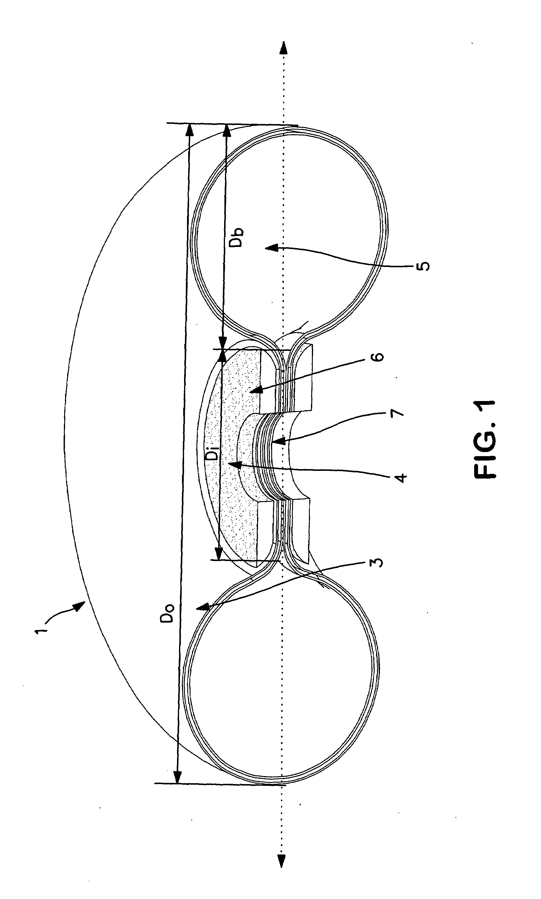
[0011]The present invention is a toroidal-shaped balloon catheter for use in a variety of surgical procedures. The toroidal-shaped balloons of the present invention can be made to reach large outer diameters and sustain high inflation pressures while maintaining their shape and can return to their pre-inflation shape upon deflation. In addition, the toroidal-shaped balloons of the present invention can be made to provide

Problems solved by technology

However, because the balloon portion of the catheter is not visible to the physician, the balloon may be over inflated without the physician's awareness.
While the inelastic material of the balloon is generally effective in compacting deposits, it tends to collapse unevenly upon deflation, leaving a flattened, folded balloon substantially larger in cross section than the balloon was prior to inflation.
This enlarged, folded balloon may be difficult to remove, especially from small vessels.
The weak nature of the elastomer material used in these types of balloon catheters has restricted their use to small diameter balloon applications; typically less than 4 to 5 mm diameter.
The means for reinforcing the elastic balloon catheters to date have not addressed both the low profile and high burst pressure requirements for large diameter balloon applications.

Method used


Image

  • Inflatable toroidal-shaped balloons
  • Inflatable toroidal-shaped balloons
  • Inflatable toroidal-shaped balloons

Examples


example 1

Composite Film Preparation

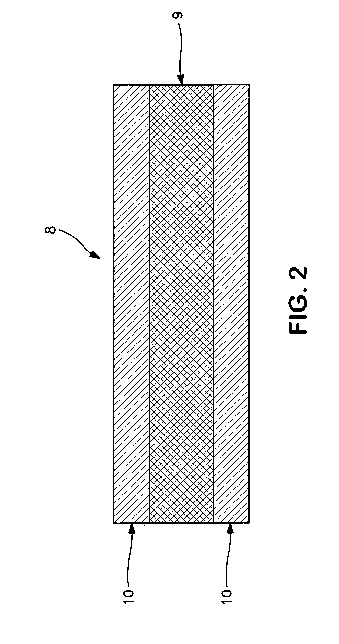
[0050]A composite film was made by using a wire-wound rod coating process whereby a solution of Tecothane TT-1085A polyurethane and tetrahydrofuran (THF) was coated onto an ePTFE membrane. The ePTFE membrane used to make the composite film was made in accordance with general the teaching in U.S. Pat. No. 5,476,589. Specifically, the ePTFE membrane was longitudinally expanded to a ratio of 55 to 1 and transversely expanded approximately 2.25 to 1, to produce a thin strong membrane with an mass of approximately 3.5 g / m2 and a thickness of approximately 6.5 micrometers. A 3% to 8% by weight solution of Tecothane TT-1085A polyurethane in THF was coated onto the ePTFE membrane to produce a composite film with approximately equal amounts of Tecothane TT-1085A polyurethane on either side and throughout the ePTFE membrane and a total polymer weight application of approximately 40% to 60% of the total final composite film weight.

example 2

Toroidal-Shaped Balloon

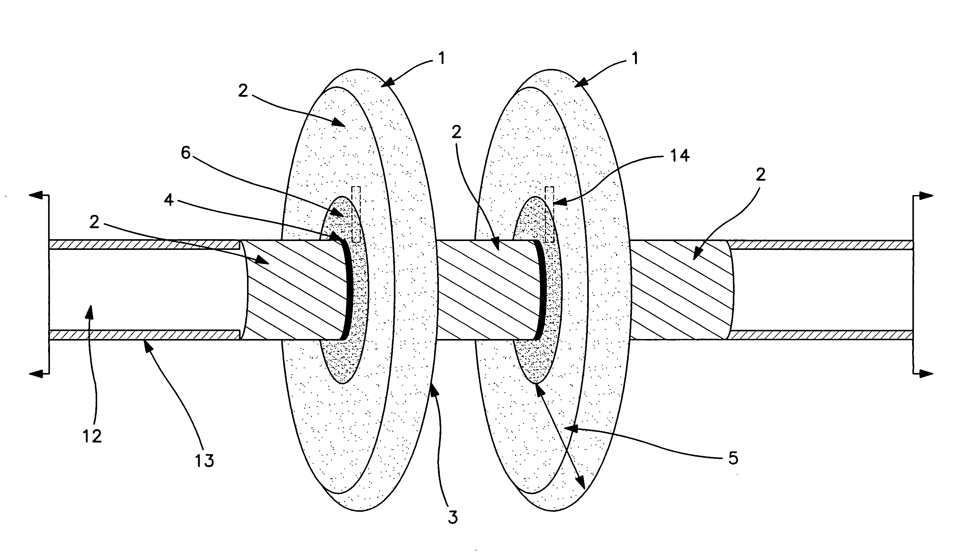
[0051]A 30.5 cm long, 4.8 mm outer wall diameter stainless steel tube was cigarette wrapped with two layers of an expanded PTFE membrane and EFEP (ethylene-perfluoroethylenepropene) fluoroplastic composite with the EFEP layer facing the stainless steel tube. This ePTFE / EFEP composite film was wrapped around the tube to provide a low friction slip layer. The ePTFE membrane / EFEP composite was approximately 50 um thick. The wrapped tube was then placed into a convection oven set to 250° C. for 30 minutes. An approximately 1.5 mm diameter hole was drilled through one side of a hollow stainless steel tube, approximately centered along the length.

[0052]A first pass with 2.5 cm wide composite film as described in Example 1 was helically wrapped around the center 15 cm long section of stainless steel tube at approximately 10 degrees from the longitudinal axis of the tube. The second pass of 2.5 cm wide composite film was then wrapped in the opposite direction at the s...

example 3

Test Methods

[0058]Tensile Break Load Measurements and Matrix Tensile Strength Calculations Tensile break load was measured using an INSTRON 1122 tensile test machine equipped with flat-faced grips and a 0.445 kN load cell. The gauge length was 5.08 cm and the cross-head speed was 50.8 cm / min. The sample dimensions were 2.54 cm by 15.24 cm. For longitudinal MTS measurements, the larger dimension of the sample was oriented in the machine, also known as the down web direction. For the transverse MTS measurements, the larger dimension of the sample was oriented perpendicular to the machine direction, also known as the cross web direction. Each sample was weighed using a Mettler Toledo Scale Model AG204, then the thickness of the samples was taken using the Kafer FZ1000 / 30 thickness gauge. The samples were then tested individually on the tensile tester. Three different sections of each sample were measured. The average of the three maximum load (i.e., the peak force) measurements was use...


PUM


Abstract

An inflatable toroidal-shaped balloon for medical use is provided with a central opening traversing the balloon in an inflated state. The balloon is useful to achieve larger outer diameters than conventional balloons.

Description

BACKGROUND OF THE INVENTION[0001]The present invention relates to inflatable balloons and more particularly to inflatable toroidal-shaped balloon catheters for medical procedures.[0002]Balloon catheters are well known in the art. Such catheters are employed in a variety of medical procedures, including dilation of narrowed blood vessels, placement of stents and other implants, and temporary occlusion of blood vessels, and other vascular uses.[0003]In a typical application, the balloon is advanced to the desired location in the vascular system. The balloon is then pressure-expanded in accordance with a medical procedure. Thereafter, the pressure is removed from the balloon, allowing the balloon to contract and permit removal of the catheter. It is to be appreciated that the balloon is preferably formed of an elastomeric material which is readily pressure-expanded, yet will also readily contract upon removal of the inflation pressure.[0004]Procedures such as these are generally consid...

Claims


Application Information

Patent Timeline
IPC IPC(8): A61M29/00A61M31/00A61M37/00A61F2/958
CPCA61L29/126A61L29/148A61M25/1002A61M2025/1075A61M25/1029A61M29/02A61M2025/105A61M25/1011
Inventor TOWLER, JEFFREY
Owner WL GORE & ASSOC INC
Learn More