Concentrator Solar Photovoltaic Power Generating Apparatus

a solar photovoltaic and concentrator technology, applied in the safety of solar heat collectors, solar heat systems, lighting and heating devices, etc., can solve the problems of deterioration of solar cells, inability to avoid being deteriorated, and difficulty in ensuring the thickness of wiring ribbons is sufficiently sealed with sealing resin, so as to prevent deterioration of transparent resin members, the effect of high durability

Inactive Publication Date: 2008-04-17
DAIDO STEEL CO LTD
View PDF14 Cites 93 Cited by
  • Summary
  • Abstract
  • Description
  • Claims
  • Application Information

AI Technical Summary

Benefits of technology

[0017] In the concentrator solar photovoltaic power generating apparatus according to the first aspect of the invention, since it is provided with the transparent resin member which is interposed between the bottom end surface of the columnar optical member and the solar cell, and the shielding member for shielding the transparent resin member from sunlight, the bonded surface is not damaged due to deterioration of the transparent resin member by light, and consequently, deterioration of the solar cell due to entering moisture is restrained and high durability of the concentrator solar photovoltaic power generating apparatus is achieved.
[0018] In the apparatus according to the second aspect of the invention, since the shielding member is the non-transparent colored resin member which covers the transparent resin member, the non-transparent colored resin member prevents deterioration of the transparent resin member by sunlight that is difficult to reach the transparent resin member.
[0019] In the apparatus according to the third aspect of the invention, since the non-transparent colored resin member is the white resin member including the filler which is constituted by the white and non-transparent powder, and is disposed so as to cover the outer circumferential surface of the bottom end portion of the columnar optical member, the sunlight directing outwards through the outer surface in the bottom end portion of the columnar optical member is reflected by a plurality of times and reach the solar cell, and consequently, further higher generation efficiency is achieved. Especially, a remarkable effect as described ab...

Problems solved by technology

Moisture due to dew formation in the housing of the concentrator solar photovoltaic power generating apparatus described above at night, causes further deterioration of solar cells.
(a) The above-indicated transparent resin formed of a material having superior optical characteristics such as silicone resin or epoxy resin, cannot avoid being deteriorated due to travel of sunlight having high energy through the transparent material.
(b) A thick wiring ribbon to which a comparat...

Method used


Image

  • Concentrator Solar Photovoltaic Power Generating Apparatus
  • Concentrator Solar Photovoltaic Power Generating Apparatus
  • Concentrator Solar Photovoltaic Power Generating Apparatus

Examples


embodiment 1

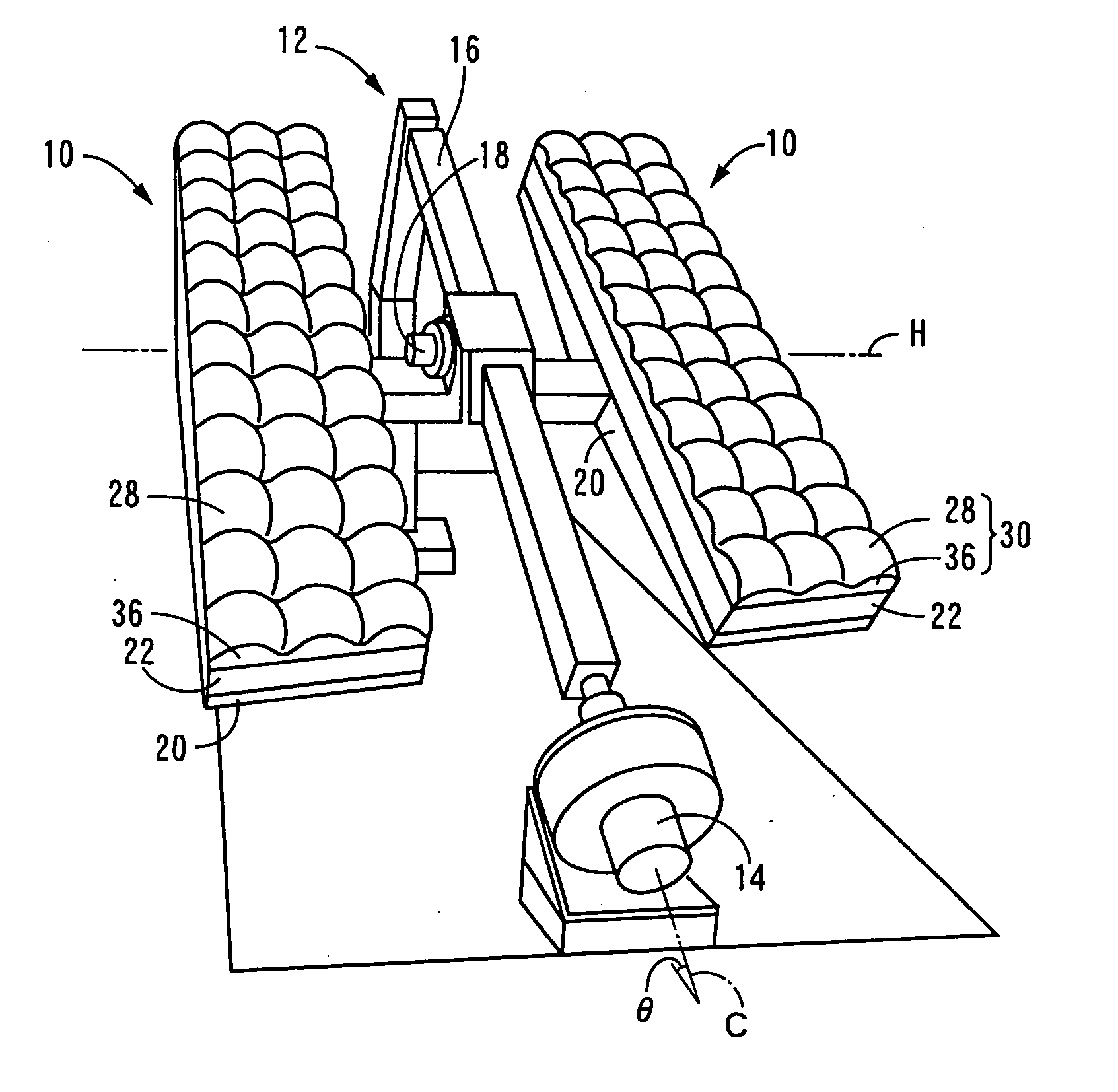
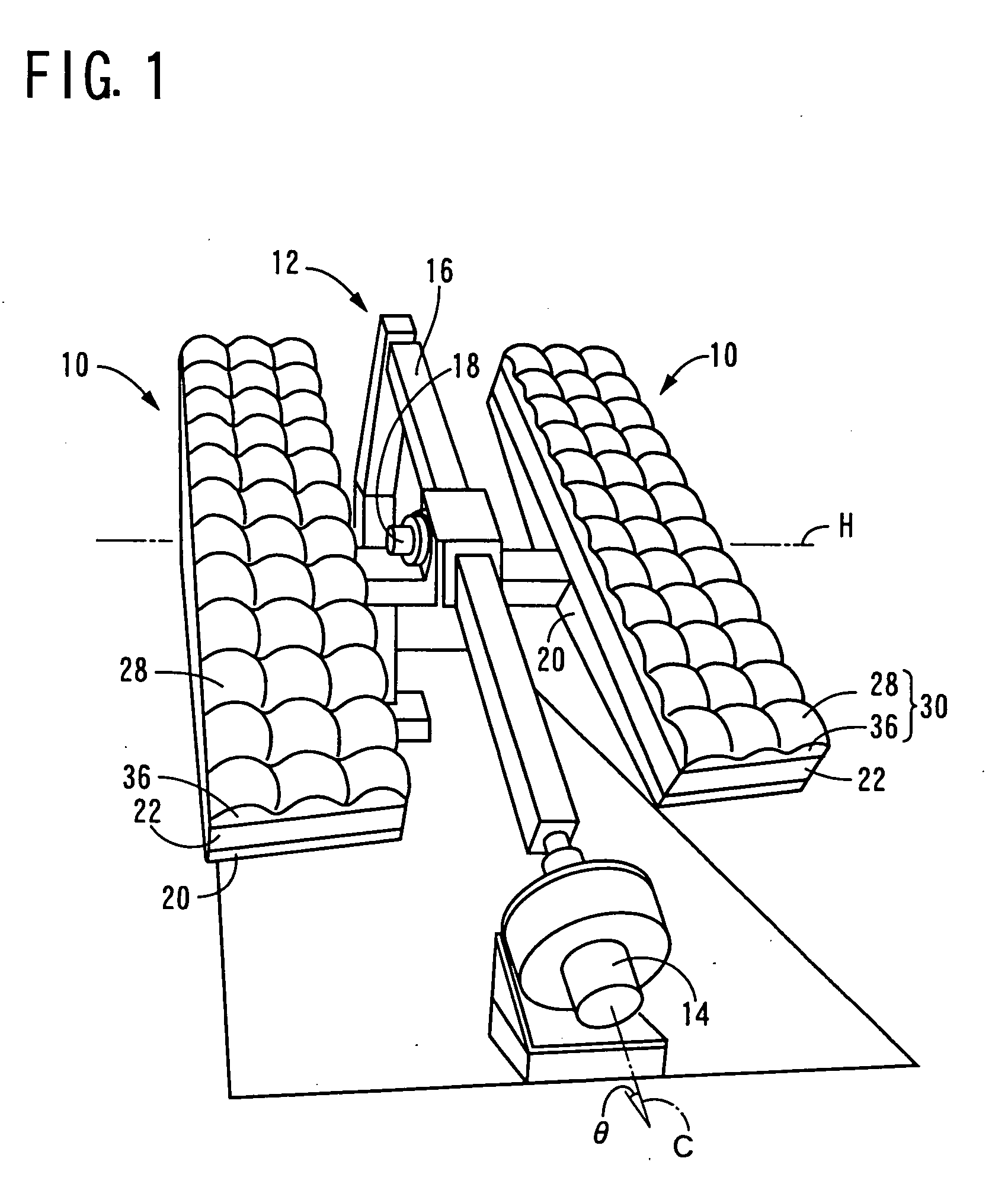
[0058]FIG. 1 illustrates a concentrator solar photovoltaic power generating apparatus 10 according to one embodiment of the present invention which a sun tracking apparatus 12 is furnished with, in a perspective view. The sun tracking apparatus 12 is configured to move and constantly direct the apparatus 10 to the sun. The apparatus 12 includes a tracking motor 14, an inclined beam 16, an altitude correction motor 18 and a pair of backing plates 20. The inclined beam 16 is rotatably mounted around an inclined axis C which is inclined by a predetermined angle θ, namely, an angle corresponding to the latitude, from the horizontal plane so that the beam 16 is placed and extends parallel to the earth's axis. And the tracking motor 14 with a reduction gear changes the rotation angle of the inclined beam 16 around the inclined axis C. The backing plates 20 are rotatably mounted around the horizontal axis H at the intermediate portion of the inclined beam 16. And the altitude correction mo...

embodiment 2

[0075]FIGS. 6, 7 and 8 illustrate results of durability tests by the inventors. FIG. 6 illustrates changes in relative amounts of power generation that were measured under concentrated ultraviolet radiation corresponding to the accumulated amount for exposure for the not less than 20-year equivalence in the positively or intentionally induced dew formation environment at the temperature of 20° C. by water cooling, with respect to a generation module F provided with the same white resin member 64 and the anti-reflection layer (TiO2 / Al2O3) 52 as in the above-described embodiment, a generation module E with the anti-reflection layer 52 of which the material is replaced by ZnS / MgF2, the only difference between the module F and E, and generation modules A, B, C and D with transparent silicone resin member by which the white resin member 64 in the module F is replaced. It was found that the relative generation amount of the generation module A with the transparent silicone resin member in...

embodiment 3

[0078]FIG. 9 illustrates the results measured of an accelerating environment test by the inventors for durability. After prepared samples of 0 wt %, 2 wt %, 5 wt %, 10 wt %, 20 wt %, 30 wt % and 50 wt % of the rate of fluorosilicone resin mixed into the white resin member 64 in the generation module 40 constructed as described above, those generation module samples were placed in an accelerating environment test tank maintained at the temperature of 85° C. and the relative humidity of 85%. Outputs from the generation module samples were measured at every predetermined time (or day).

[0079] In FIG. 9 the longitudinal axis shows the relative output value to the initial generation output value that was regarded as 1, and lateral axis shows the elapsed time. The effect for 2000 hours in the above accelerating environment test corresponds to that for six years in the outdoor. In general it is regarded as practically effective if the relative output of not less than 70% is maintained, tha...


PUM


Abstract

A concentrator solar photovoltaic power generating apparatus including a primary optics for concentrating sunlight, a solar cell, a columnar optical member which is vertically disposed above the solar cell so that a bottom end surface of the columnar optical member is opposed to the solar cell, and which is used for guiding the sunlight which is concentrated by the primary optics to the solar cell, a transparent resin member which is interposed between the bottom end surface of the columnar optical member and the solar cell, comprises a shielding member for shielding the transparent resin member from sunlight.

Description

TECHNICAL FIELD [0001] The present invention relates to a concentrator solar photovoltaic power generating apparatus in which sunlight is focused by a primary optics onto a small but highly efficient solar cell, particularly, to technique to provide the apparatus with high durability. BACKGROUND ART [0002] The concentrator solar photovoltaic power generating apparatus draws public attention. Sunlight can be collected from a large area using cheap materials, such as plastic, but the power conversion is performed by a high performance solar cell (as disclosed, for example, in Non-Patent Document 1 described below). In this apparatus, the concentrated light that is concentrated in the primary optics has unevenness in its intensity, such as high intensity in its center and low intensity in its surroundings. Non-Patent Document 2, for example, points out that, consequently, direct irradiation to the solar cell with the concentrated light that is concentrated in the primary optics causes ...

Claims


Application Information

Patent Timeline
IPC IPC(8): H01L31/04
CPCF24J2/06F24J2/085F24J2/4621H01L31/0547Y02E10/52H01L31/0543F24J2/5427F24S23/00F24S23/31F24S30/458F24S40/50F24S50/20Y02E10/47
Inventor ARAKI, KENJIYANO, TAIZOUOZUMI, HISAFUMI
Owner DAIDO STEEL CO LTD
Why Eureka
Try Eureka