Electrified ceiling framework

a ceiling framework and electrical technology, applied in the direction of insulated conductors, cables, coupling device connections, etc., can solve the problems of difficult service or reconfiguration, increased fraction of devices found in those buildings that actually operate on low voltage direct current, and limited installation of devices utilizing low voltage dc, so as to reduce wiring, convenient and convenient connection, and convenient routing

Inactive Publication Date: 2008-04-17
WORTHINGTON ARMSTRONG VENTURE
View PDF38 Cites 43 Cited by
  • Summary
  • Abstract
  • Description
  • Claims
  • Application Information

AI Technical Summary

Benefits of technology

[0011]Still another advantage of the present invention is that a variety of low voltage electrical devices may be safely and conveniently connected to or unconnected from the electrified ceiling framework while the source of low voltage power remains on and connected to the conductive material of the framework.
[0012]Still another advantage of the present invention is that all or a portion of the system may be fabricated during the manufacture of the support members or may be retrofitted to installed support members.
[0013]Still another advantage of the present invention is that the system utilizes low voltage technology providing the ability to power electrical, electronic or other electro-active devices without the need to convert the power from AC to DC for each device.
[0014]Still another advantage of the present invention is that the low voltage power transmitted through the conductive material of the electrified ceiling framework may be conveniently routed in alternate pathway configurations by means of placing either non-switchable or switchable non-conductive or conductive interconnecting shunt devices at one or a plurality of junctions points of said conductive material within said framework.
[0015]Still another advantage of the present invention is that one or a plurality of the electrical devices connected to the conductive material of the electrified ceiling framework may be controlled, monitored, or otherwise communicated with via a wireless signaling means wherein at least one transmitter, receiver or transceiver element in the communication link is powered by being connected to the conductive material of the electrified ceiling framework, thus further reducing wiring and / or the use of batteries or similar discrete power means that would otherwise be needed.
[0016]Still another advantage of the present invention is that one or a plurality of the electrical devices connected to the conductive material of the electrified ceiling framework may be designed to operate in one or a plurality of different operational modes based on controlled or uncontrolled changes in the level of power available, for example, as may be occasioned by the purposeful or accidental loss or reduction of power from one or a plurality of the system's low voltage power sources.

Problems solved by technology

Yet, an increasing fraction of devices found in those buildings actually operate on low voltage direct current (DC).
Installation of devices utilizing low voltage DC has been typically limited to locations in which either a pair of wires carrying high voltage AC are routed to the device that has a self-contained ability to convert the AC power to a useful form of low voltage DC power or where a pair of wires are routed from a separate source of useful low voltage DC power.
The grid framework and ceiling tile system may provide a visual barrier between the living or working space and the infrastructure systems mounted overhead.
These known systems suffer from the drawback that the network of wires required occupy the limited space above the ceiling grid, and are difficult to service or reconfigure.
Moreover, the techniques currently used are limited in that the electricity that is provided to the ceiling environment is not reasonably accessible from all directions relative to the ceiling plane.
Further, the electrical power levels that are typically available are not safe for those not trained, licensed and / or certified in the practice to work with.

Method used


Image

  • Electrified ceiling framework
  • Electrified ceiling framework
  • Electrified ceiling framework

Examples


Embodiment Construction

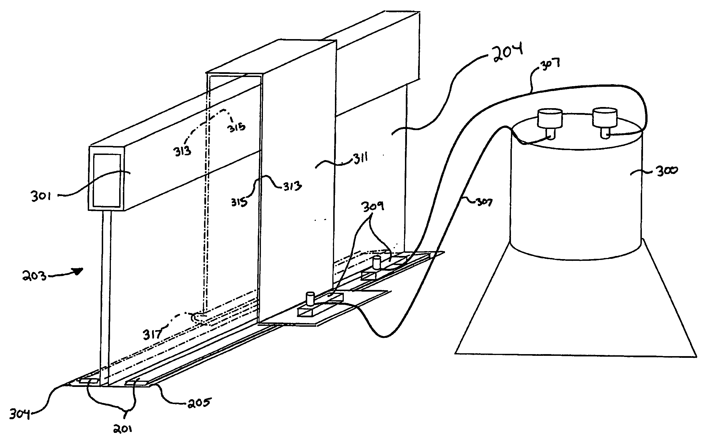
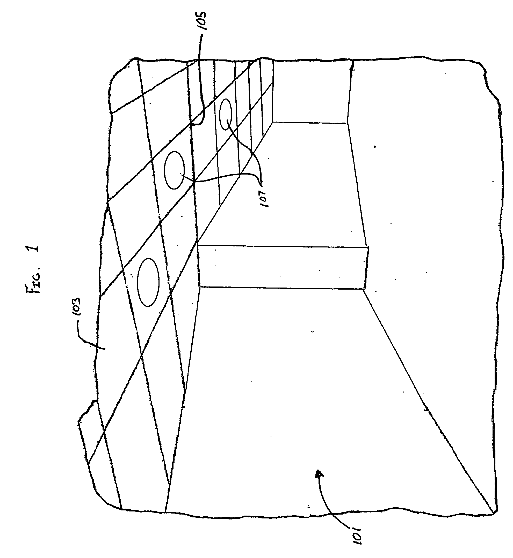
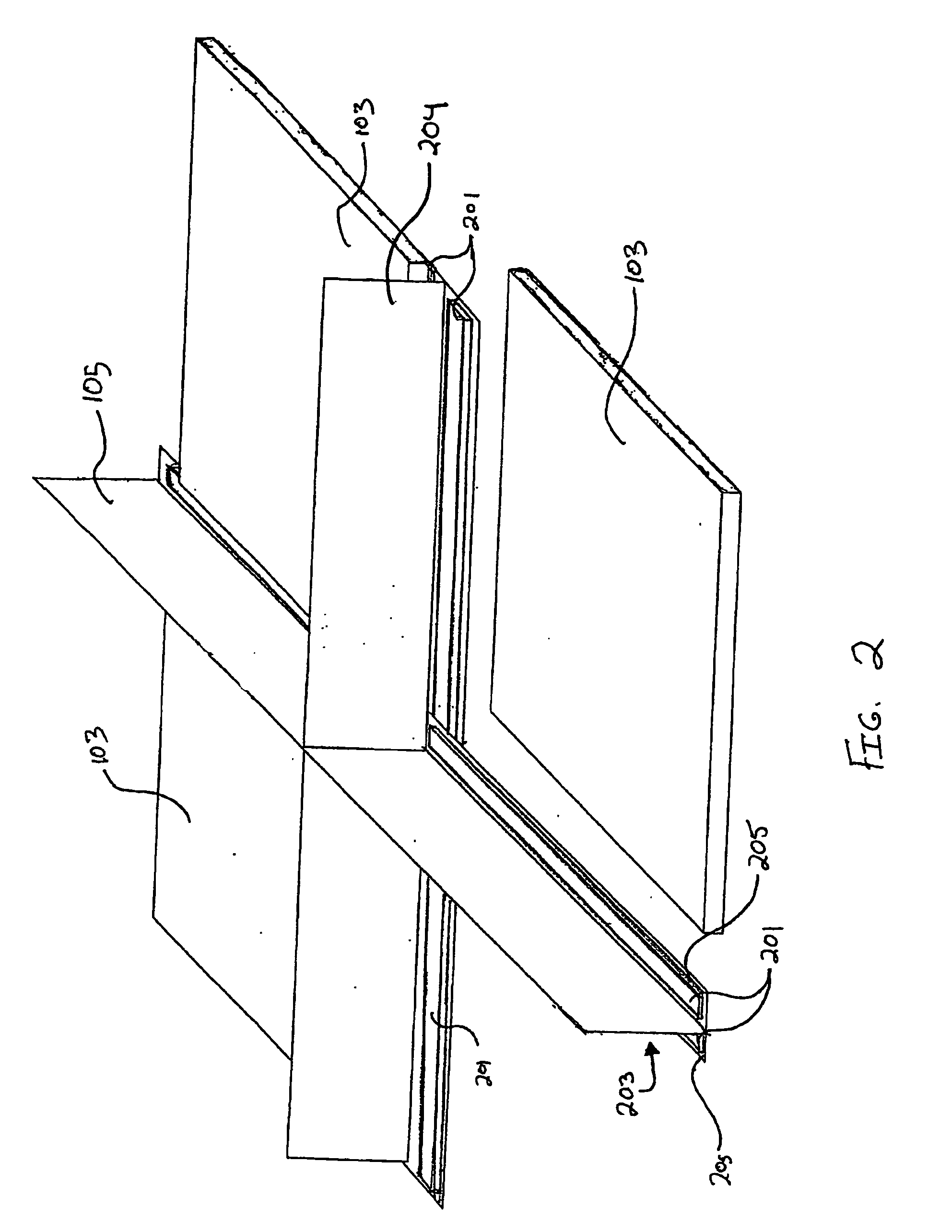
[0027]The present invention includes an electrified ceiling framework. In particular, the present invention includes a framework, preferably mounted onto the structural overhead of a room space 101, that is capable of providing power to low voltage devices 107. FIG. 1 shows a room space 101 having a ceiling 103 supported by a ceiling grid framework 105. The ceiling 103 may include decorative tiles, acoustical tiles, insulative tiles, lights, heating ventilation and air conditioning (HVAC) vents, other ceiling elements or covers and combinations thereof. Low voltage devices 107 include, but are not limited to decorative devices, lighting devices, such as incandescent lights, fluorescent lights, light emitting diode (LED) lights, organic light emitting diode (OLED) lights, polymer light emitting diodes, electroluminescent lights, acoustical devices, such as speakers, heating or cooling devices, such as electrically actuated mechanical devices (i.e. variable air velocity diffusers), se...


PUM


Abstract

An electrified ceiling framework system having a plurality of grid elements forming a grid network arranged in a substantially planar arrangement. A conductive material is disposed on a surface of at least one of the plurality of grid elements. The conductive material is electrically connected to a low voltage power source and has a contact surface connectable to a low voltage device.

Description

FIELD OF THE INVENTION[0001]The present invention is directed to ceiling grid frameworks. Specifically, the present invention is directed to electrified ceiling grid frameworks for connection to low voltage devices.BACKGROUND OF THE INVENTION[0002]The electrical grid connecting America's power plants, transmission lines and substations to homes, businesses and factories operate almost entirely within the realm of high voltage alternating current (AC). Yet, an increasing fraction of devices found in those buildings actually operate on low voltage direct current (DC). Those devices include, but are not limited to, digital displays, remote controls, touch-sensitive controls, transmitters, receivers, timers, light emitting diodes (LEDs), audio amplifiers, microprocessors, other digital electronics and virtually all products utilizing rechargeable or disposable batteries.[0003]Installation of devices utilizing low voltage DC has been typically limited to locations in which either a pair ...

Claims


Application Information

Patent Timeline
Patent Type & Authority Applications(United States)
IPC IPC(8): H02G3/04
CPCH02G3/381H01R25/147
Inventor PATTERSON, BRIAN T.FRECSKA, SANDORMYERS, JERE W.
Owner WORTHINGTON ARMSTRONG VENTURE
Why Eureka
Try Eureka