Elevated electrodes for probe position sensing

a position sensing and electrode technology, applied in the field of probe storage devices, can solve the problems of high speed, low error-rate readout, and data can then be read out destructively, and achieve the effect of increasing capacitance and low friction

Inactive Publication Date: 2008-04-17
SEAGATE TECH LLC
View PDF29 Cites 22 Cited by
  • Summary
  • Abstract
  • Description
  • Claims
  • Application Information

AI Technical Summary

Benefits of technology

[0013]In another aspect, the invention provides an apparatus comprising a storage medium, a head substrate, wherein the storage medium and the head substrate are separated by a gap, a plurality of posts positioned in the gap, and a layer of low friction material positioned on one end of each of the posts.
[0014]The invention further encompasses an apparatus comprising a storage medium, a head substrate, wherein the storage medium and the head substrate are separated by a gap, and a plurality of electrodes separated from each other to form sensor capacitors, wherein some of the electrodes extend into the gap to increase the capacitance between the electrodes.

Problems solved by technology

A sense amplifier measures the charge flow that results when the polarization switches, so that a current pulse is observed for cells which stored a “0”, but not for cells which stored a “1”, thus providing a destructive readback capability.
Data can then be read out destructively by applying a voltage of a magnitude and polarity such as to cause the polarization to point “up”.
However, for a typical domain size of 25 nm×25 nm, desirable for an FE-Probe device, the resulting charge would be limited to about 6000 electrons, giving a current of about 1 nA for a read time of 1 microsecond, which makes high-speed, low error-rate readout difficult.
In addition, the readback is necessarily destructive, i.e., not preserving the original data.
Standard tips manufactured for Scanning Probe Microscopy (SPM) do not meet these requirements.
One of the challenges in designing probe storage devices is obtaining accurate position feedback for servo loops.
Such high track densities place great demands on the servo positioning system.
One of the challenges in the probe storage area is maintaining accurate spacing between the head and media wafers.
Variations in this spacing could modify the contact force, angle, and position of the probe head against the media wafer, thus potentially introducing noise in read and write and compromising the reliability of the head and the media mechanical interfacing.
Vibration and shock are expected to result in dynamic changes in the head and media spacing for a given device.
Unfortunately these springs may also allow vertical motions and tilting motions in the presence of external disturbances.
In the worst case, the probe heads may lose contact with the media.
The high-aspect-ratio springs are difficult to manufacture using conventional (non-MEMS) technology and could not easily provide the required vertical stiffness and horizontal flexibility simultaneously.
Active control (of vertical translation and two axes of tilt) requires additional mechanics and electronics for the actuators and control circuitry, which are prohibitive given the tight space and power budget.

Method used


Image

  • Elevated electrodes for probe position sensing
  • Elevated electrodes for probe position sensing
  • Elevated electrodes for probe position sensing

Examples


Embodiment Construction

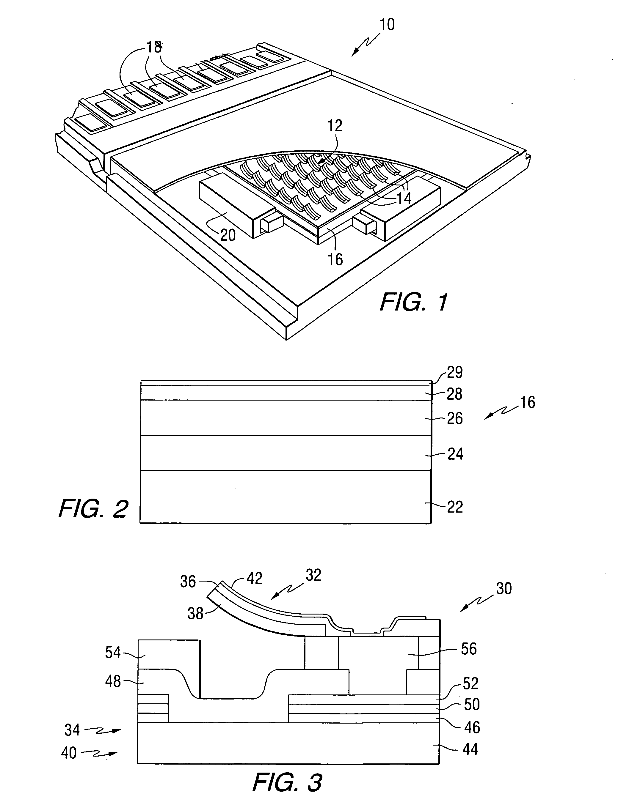
[0044]This invention provides probe storage devices that include a ferroelectric storage medium. FIG. 1 is a perspective view of a ferroelectric storage device 10, which illustrates an implementation of a storage system constructed in accordance with the present invention. In the ferroelectric storage device 10 of FIG. 1, an array 12 of ferroelectric heads 14 is positioned adjacent to a storage medium 16. In the configuration shown in FIG. 1 the array 14 and the medium 16 are planar and extend generally parallel with each other. The array 14 comprises a plurality of electrodes, which are operably coupled to connectors 18. The storage medium 16 is coupled to at least one actuator 20, which is configured to move the medium 16 relative to array 12. This movement causes the ferroelectric heads to be moved relative to the individual ferroelectric domains on medium 16. Each head can include one or more electrodes. To address the destructive readback of data, one technique maintains at lea...


PUM

PropertyMeasurementUnit
thicknessaaaaaaaaaa
thicknessaaaaaaaaaa
thicknessaaaaaaaaaa

Abstract

An apparatus comprises a storage medium, a head substrate, wherein the storage medium and the head substrate are separated by a gap, a plurality of electrodes separated from each other, and a support structure positioned in the gap for supporting some of the electrodes. An apparatus comprising a storage medium, a head substrate, wherein the storage medium and the head substrate are separated by a gap, a plurality of posts positioned in the gap, a layer of low friction material positioned on one end of each of the posts, is also described.

Description

FIELD OF THE INVENTION[0001]This invention relates to data storage devices, and more particularly to probe storage devices that include ferroelectric storage media.BACKGROUND OF THE INVENTION[0002]Ferroelectric materials can form the basis for data storage devices, where digital “1” and “0” levels are represented by the electric polarization of a ferroelectric film pointing “up” or “down”. Storage devices based on a ferroelectric storage medium include Ferroelectric Random Access Memory (FeRAM) and scanning probe storage systems (“FE-Probe”).[0003]In an FeRAM memory cell the essential storage element includes a thin ferroelectric film sandwiched between fixed, conductive electrodes. To write a bit to such a cell, a voltage pulse of either positive or negative polarity is applied between the electrodes in order to switch the internal polarization of the ferroelectric film to the “up” or “down” state, respectively. To read back the data from the FeRAM cell, a read voltage of a certain...

Claims


Application Information

Patent Timeline
Patent Type & Authority Applications(United States)
IPC IPC(8): G11B9/00
CPCB82Y10/00G11B9/1481G11B9/02
Inventor CHU, PATRICK BRECKOWBEDILLION, MARK DAVIDJOHNS, EARL CHRZASZCZLUTWYCHE, MARK IAN
Owner SEAGATE TECH LLC
Why Eureka
Try Eureka