Electro Mechanical Brake

a technology of electronic brakes and mechanical brakes, applied in the field of electronic mechanical brakes, can solve the problems of wire breaking, interference with parts, and difficult wiring layout of harnesses, and achieve the effects of reducing enhancing motor control accuracy, and increasing the number of harnesses

Inactive Publication Date: 2008-04-17
HITACHI LTD
View PDF32 Cites 40 Cited by
  • Summary
  • Abstract
  • Description
  • Claims
  • Application Information

AI Technical Summary

Benefits of technology

[0011]These problems emerge prominently as the harness becomes longer, and higher the number of harness is, greater the possible occurrence of these problems is, and a mechanical brake destined to maintain reliability is required to enhance motor control accuracy.
[0012]Hence, the present invention is required to reduce the number of harnesses, suppress a voltage drop to drive the motor, and perform a motor control considering the voltage fluctuation. Further, in order to prevent a malfunction of the brake system, it is necessary to secure noise resistance of the sensor signal.
[0013]The present invention integrates the ECU and the caliper so as to shorten the distance between various sensors a

Problems solved by technology

Hence, a wiring layout of the harness becomes difficult, and this leads to interference with parts around the wheel comprised of many parts.
Moreover, to avoid such interference, when a bending or a twisting is applied on the harness, an excessive stress is applied on a conductive wire, and a problem such as breaking of wire is caused.
Further, when the caliper and the ECU are separated, interposition of the harness between inverters driving a motor existing inside the caliper and a motor existing inside the ECU caus

Method used


Image

  • Electro Mechanical Brake
  • Electro Mechanical Brake
  • Electro Mechanical Brake

Examples


Embodiment Construction

[0035]An embodiment of an electro mechanical brake according to the present invention will be described below with reference to the drawings.

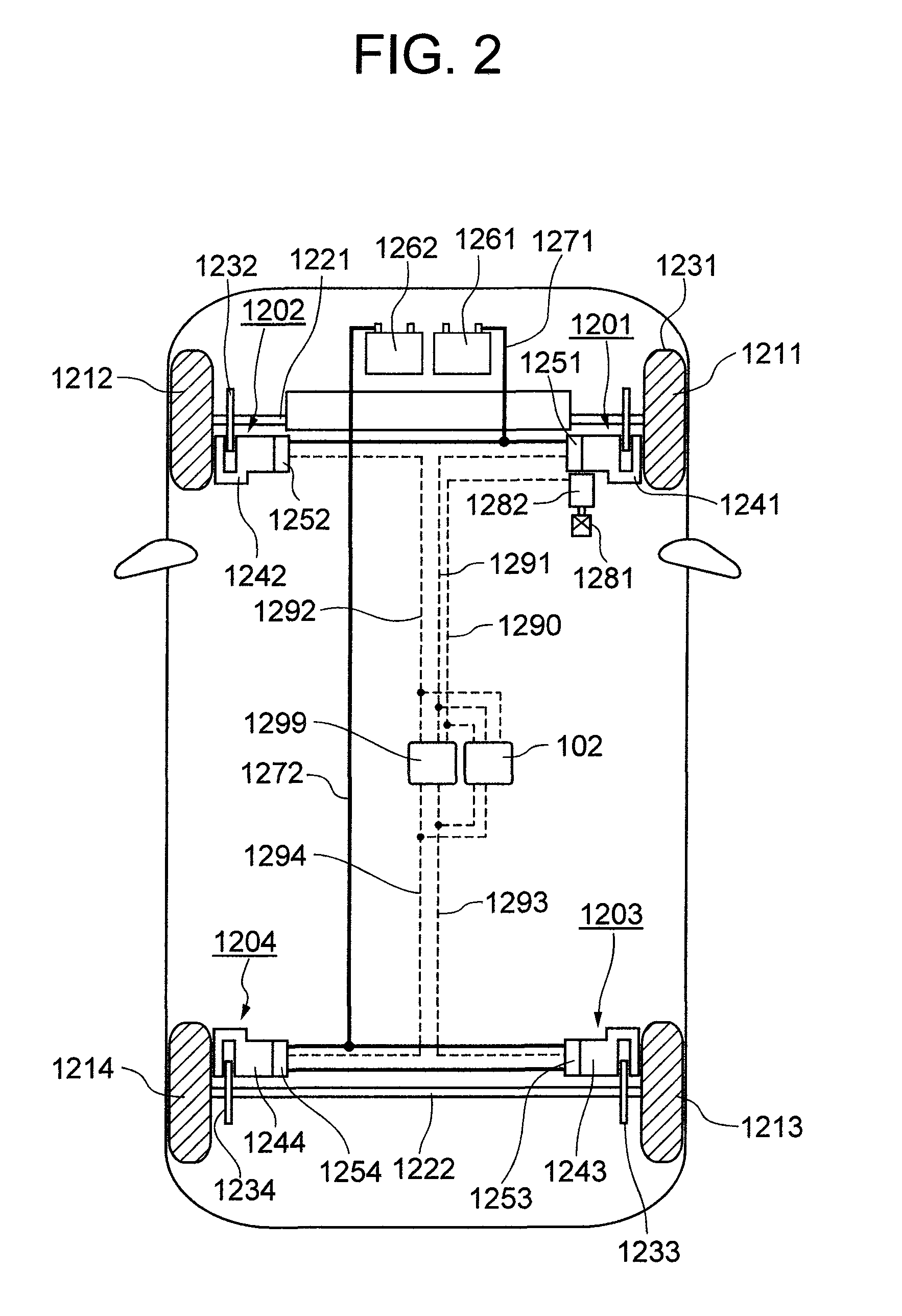
[0036]FIG. 2 is a schematic block diagram of a brake system of a vehicle mounting the electro mechanical brake comprised of one embodiment of the present invention. And, in the figure, a description of a driving mechanism for propulsion will be omitted.

[0037]A first electro mechanical brake 1201 is mounted close to a wheel shaft 1221 at a front wheel 1211 side of the right side. A second electro mechanical brake 1202 is mounted close to a wheel shaft 1221 at a front wheel 1212 side of the left side. A third electro mechanical brake 1203 is mounted close to a wheel shaft 1222 at a rear wheel 1213 side of the right side, and a fourth mechanical brake 1204 is mounted close to a wheel shaft 1222 at a rear wheel 1214 side of the left side.

[0038]While the basic structure of each of the electro mechanical brakes 1201 to 1204 is the same, the first ele...


PUM


Abstract

When a caliper and an ECU are separately configured in an electro mechanical brake, the number of harness is increased, and therefore, the wiring layout of the harness becomes difficult, and when bending and twisting are applied to the harness, a problem of a breaking of the wiring and the like arises. Further, a voltage drop is caused by the electric resistance of the harness, and moreover, there is a risk of infiltration of noises. The ECU and the caliper are integrated, thereby making the distance between various sensors and control devices short. Further, the frame body of the ECU incorporates an inverter module driving a motor and its control device, thereby simplifying a wiring connection to the motor.

Description

BACKGROUND OF THE INVENTION[0001](1) Field of the Invention[0002]The present invention relates to an electro mechanical brake generating a braking force by an electric motor.[0003](2) Description of Related Art[0004]An electro mechanical brake is a mechanical brake generating a braking force by an electric motor. This electro mechanical brake comprises an electric circuit portion controlling an output generated by the electric motor, and a mechanism portion generating a braking force based on the output of the motor. The mechanism portion is mounted on the portion close to the wheel of a vehicle, and the electric circuit portion is mounted on the spring portion of the vehicle. That is, the mechanism portion and the electric circuit portion have been mounted on the positions physically spaced apart in the vehicle.[0005]The inventors of the present patent application have considered the possibility of integrating the mechanism portion and the electric circuit portion in view of improv...

Claims


Application Information

Patent Timeline
IPC IPC(8): G06F19/00B60T15/14F16D65/18B60T13/74F16D55/225F16D65/02F16D65/14F16D66/00
CPCB60T13/741F16D65/18F16D2066/003F16D2066/005H05K7/1432F16D2125/36F16D2125/40F16D2127/06F16D2129/08F16D2121/24H05K7/14322
Inventor WATANABE, HIROFUMISUZUKI, TAKAFUMIYASUKAWA, DAISUKE
Owner HITACHI LTD
Why Eureka
Try Eureka