Internal Combustion Engine System and Internal Combustion Engine Control Method

a technology of internal combustion engine and control method, which is applied in the direction of engine starters, electric control, instruments, etc., can solve the problems of unstable stop position of internal combustion engine, undesirable vibration, insufficient diffusion of injected fuel, etc., and achieve the effect of effectively preventing potential vibration

Active Publication Date: 2008-04-17
TOYOTA JIDOSHA KK
View PDF2 Cites 24 Cited by
  • Summary
  • Abstract
  • Description
  • Claims
  • Application Information

AI Technical Summary

Benefits of technology

[0043] In response to a stop instruction of the internal combustion engine, the third internal combustion engine control method of the invention injects the fuel according to the measured crank angle at the specific fuel injection timing immediately before a stop of the internal combustion engine into the specified cylinder, which stops in the preset cycle range including part of the compression stroke when the internal combustion engine stops at the predicted stop position. When the predicted stop position of the internal combustion engine after the fuel injection at the specific fuel injection timing into the specified cylinder leads to the determination that the stop position of the specified cylinder receiving the fuel injection passes over the ignition-inducing stop position, the third internal combustion engine control method ignites the air-fuel mixture in the specified cylinder before the stop position of the specified cylinder passes over the ignition-inducing stop position. This arrangement desirably retains unexpected combustion of the air-fuel, mixture caused by, for example, spontaneous ignition in the specified cylinder receiving the fuel injection, thus effectively preventing potential vibrations due to the unexpected combustion.
[0044] In response to a start instruction of the internal combustion engine, any of the first through the third internal combustion engine control methods may control the fuel injection unit and the ignition unit according to the crank angle measured by the crank angle measurement unit to ignite the air-fuel mixture at a first ignition timing in the specified cylinder, which stops in the preset cycle range, and to start the internal combustion engine. This arrangement ensures a quick start of the internal combustion engine.

Problems solved by technology

In a port injection-type internal combustion engine, this may lead to insufficient diffusion of the injected fuel.
The varying conditions and the aged deterioration of the internal combustion engine may cause the unstable stop position of the internal combustion engine.
When the cylinder receiving the fuel injection approaches to the top dead center of the compression stroke, a compression-induced temperature rise may cause spontaneous ignition and combustion of the air-fuel mixture and lead to undesirable vibrations due to the unexpected combustion.
This makes the driver feel something is wrong in an automobile equipped with the internal combustion engine.

Method used


Image

  • Internal Combustion Engine System and Internal Combustion Engine Control Method
  • Internal Combustion Engine System and Internal Combustion Engine Control Method
  • Internal Combustion Engine System and Internal Combustion Engine Control Method

Examples


Embodiment Construction

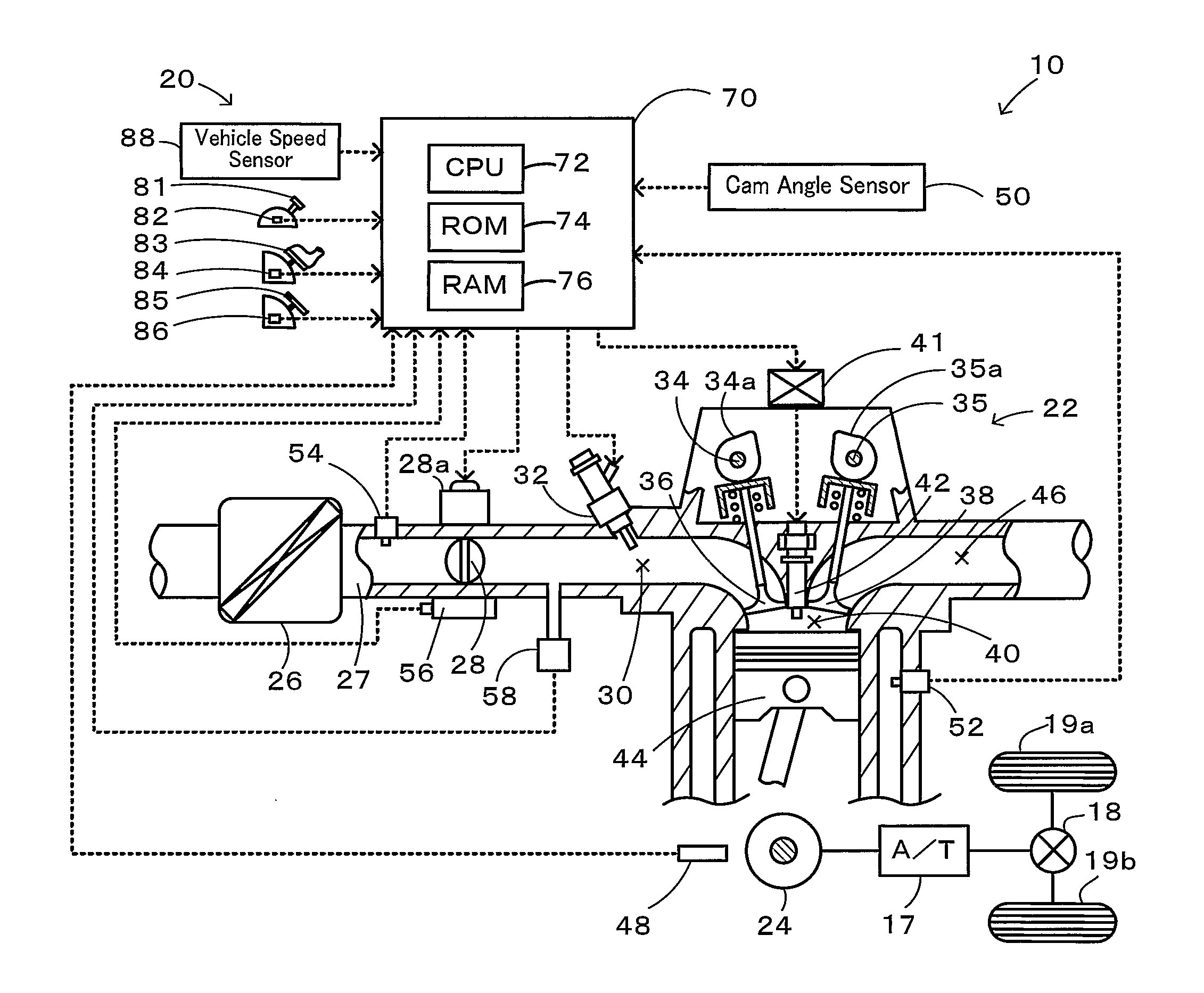
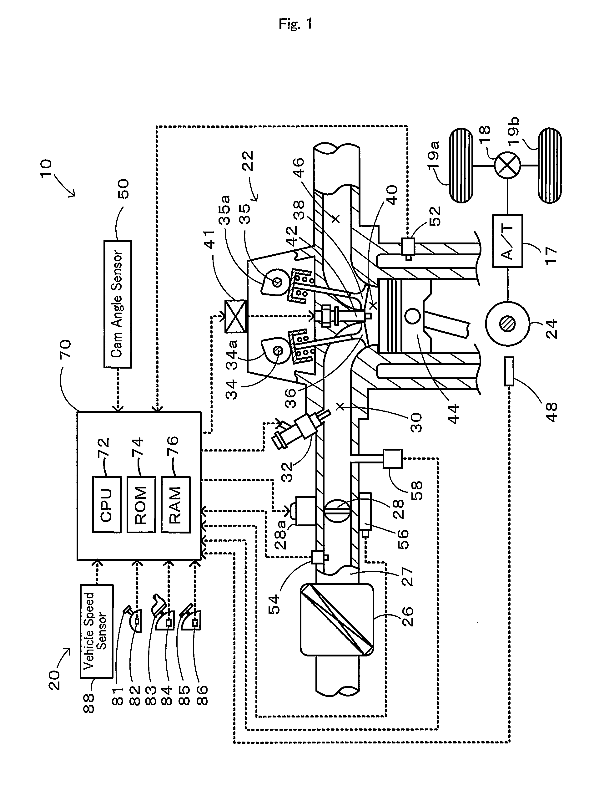
[0052] One mode of carrying out the invention is described below as a preferred embodiment. FIG. 1 schematically illustrates the configuration of a motor vehicle 10 equipped with an internal combustion engine system 20 in one embodiment of the invention. As illustrated, the motor vehicle 10 includes an engine 22 driven with gasoline, an engine electronic control unit (hereafter referred to as engine ECU) 70 that controls the engine 22, an automatic transmission (AT) 17 that converts power of a crankshaft 24 of the engine 22 and outputs the converted power to drive wheels 19a and 19b via a differential gear 18, and an AT electronic control unit (not shown) that controls the automatic transmission 17. The engine 22 and the engine ECU 70 constitute the internal combustion engine system 20 of the embodiment.

[0053] The engine 22 is an individual-injection-type 4-cylinder engine that is capable of individually injecting a supply of fuel in respective cylinders 22a to 22d of an intake man...


PUM


Abstract

The internal combustion engine control technique of the invention computes a TDC pass rotation speed Ntdc, which represents the rotation speed of an engine when one of multiple cylinders of the engine passes over a top dead center TDC (step S110). The control technique estimates an engine stop crank angle CAs from a map that is experimentally or otherwise obtained to represent a variation in TDC pass rotation speed Ntdc against the stop position of the engine (step S120), and specifies a fuel injection cylinder that stops in a preset cycle range including part of a compression stroke at a stop of the engine (step S130). The specified fuel injection cylinder receives lean fuel injection at a specific fuel injection timing (step S170). When the specified fuel injection cylinder is later presumed not to pass over a top dead center TDC of the compression stroke, a corrected amount of fuel is injected into the specified fuel injection cylinder (step S240). When the specified fuel injection cylinder is later presumed to pass over the top dead center TDC of the compression stroke, on the other hand, the control technique ignites an air-fuel mixture of the intake air and the injected fuel for combustion in the compression stroke, synchronously with fuel injection into a next cylinder that goes into the compression stroke after the specified fuel injection cylinder (step S270).

Description

TECHNICAL FIELD [0001] The present invention relates to an internal combustion engine system, an internal combustion engine control method, and a stop position prediction method that predicts a stop position of an internal combustion engine. BACKGROUND ART [0002] A proposed internal combustion engine system enables ignition of an air-fuel mixture for combustion in a cylinder having a first ignition timing at an auto restart of an internal combustion engine after its auto stop (see, for example, Japanese Patent Laid-Open Gazette No. 2001-342876). The ignition and combustion of the air-fuel mixture in the cylinder having the first ignition timing achieves a quick restart of the internal combustion engine. DISCLOSURE OF THE INVENTION [0003] In an internal combustion engine where a supply of fuel is individually injected into respective intake systems of multiple cylinders, for example, four cylinders or six cylinders, the fuel injection is generally performed in a final phase of an exh...

Claims


Application Information

Patent Timeline
Patent Type & Authority Applications(United States)
IPC IPC(8): F02D28/00F02D17/00F02D29/02F02D41/04F02D41/06F02D41/34F02D43/00F02D45/00F02N11/08F02N15/00F02N99/00
CPCF02D9/00F02D37/02F02D41/0002F02D41/0087Y02T10/42F02D41/042F02D41/062F02D2041/0095F02D41/0097Y02T10/40
Inventor TABATA, MITSUHIRONAKAMURA, MAKOTO
Owner TOYOTA JIDOSHA KK
Why Eureka
Try Eureka