Semiconductor light emitting device

a technology of semiconductors and light-emitting devices, which is applied in the direction of semiconductor devices, electrical devices, nanotechnology, etc., can solve the problems of energy band distortion phenomenon of active layers and deterioration of active layers, so as to minimize the non-uniformity of light-emitting wavelengths and reduce the luminous efficiency

Inactive Publication Date: 2008-04-24
SAMSUNG ELECTRONICS CO LTD
View PDF3 Cites 65 Cited by
  • Summary
  • Abstract
  • Description
  • Claims
  • Application Information

AI Technical Summary

Benefits of technology

[0014]Example embodiments may provide a semiconductor light emitting device in which lowering of luminous efficiency is minimized by minimizing non-uniformity of a light-emitting wavelength of an active layer having a multi-quantum well (MQW) structure.

Problems solved by technology

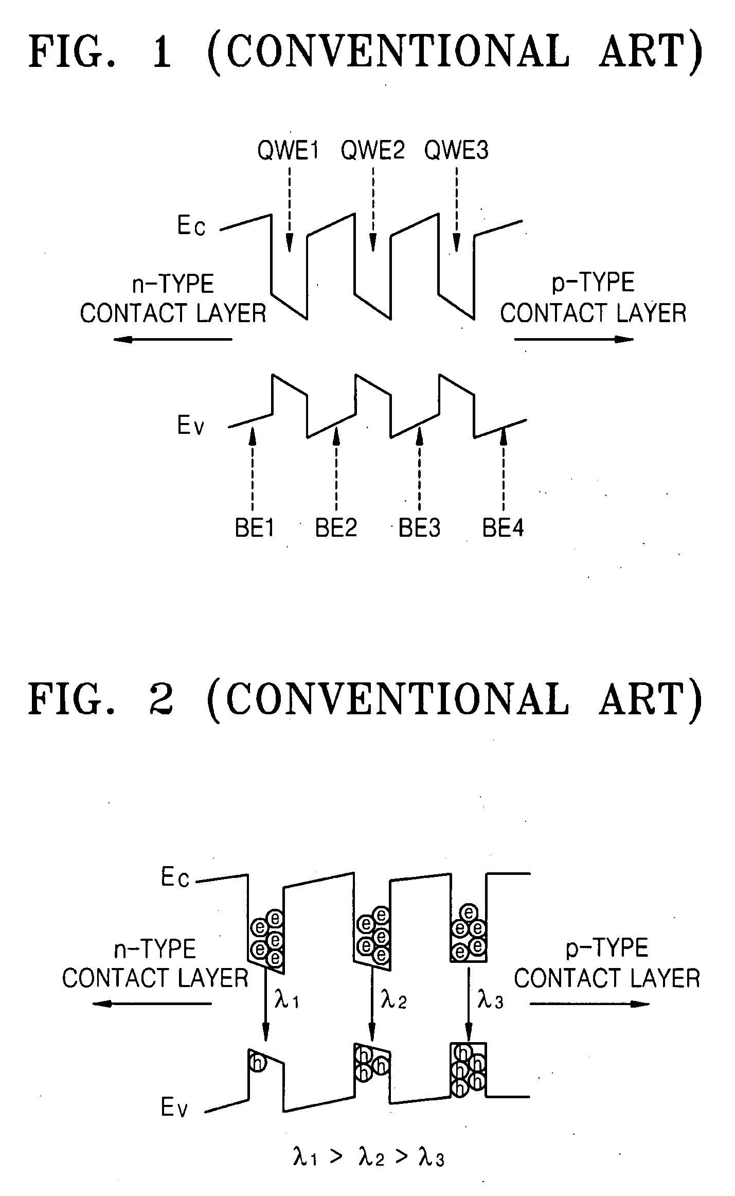
Accordingly, even if voltages are applied to the n-type contact layer and the p-type contact layer and carriers are sufficiently injected into the active layer, the energy band distortion phenomenon of the active layer may occur.
To solve this problem, a method of changing a growth surface of the quantum well layer and a method of doping a material that annihilates interface charges at the interface between the quantum well layer and the barrier layer has been suggested, however, these methods may deteriorate the characteristics of the active layer.

Method used


Image

  • Semiconductor light emitting device
  • Semiconductor light emitting device
  • Semiconductor light emitting device

Examples


Embodiment Construction

[0033]Example embodiments will now be described more fully hereinafter with reference to the accompanying drawings. Embodiments may, however, be embodied in many different forms and should not be construed as being limited to the example embodiments set forth herein. Rather, these example embodiments are provided so that this disclosure will be thorough and complete, and will fully convey the scope to those skilled in the art. In the drawings, the thicknesses of layers and regions are exaggerated for clarity.

[0034]It will be understood that when a component is referred to as being “on,”“connected to” or “coupled to” another component, it can be directly on, connected to or coupled to the other component or intervening components may be present. In contrast, when a component is referred to as being “directly on,”“directly connected to” or “directly coupled to” another component, there are no intervening components present. As used herein, the term “and / or” includes any and all combin...


PUM


Abstract

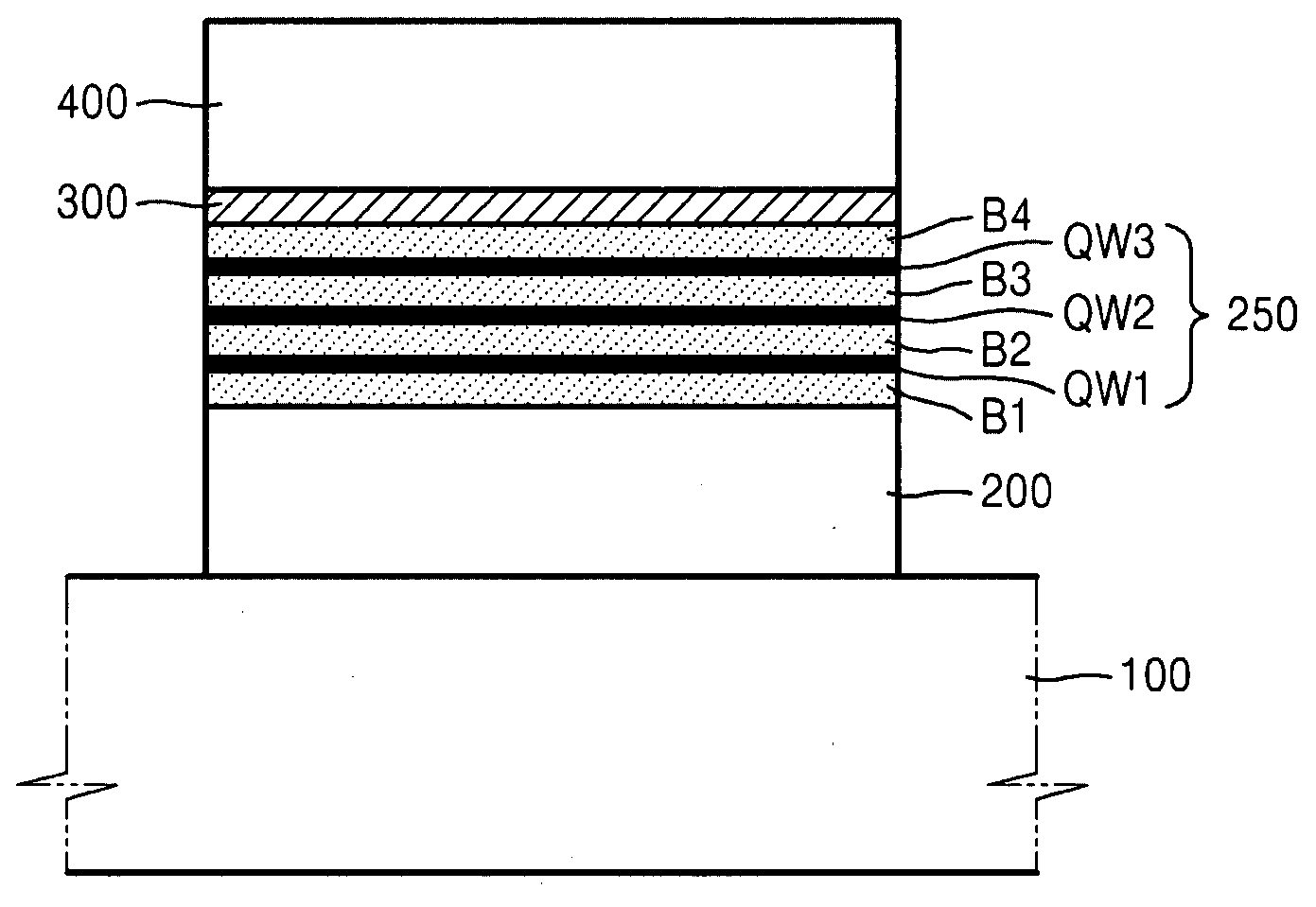
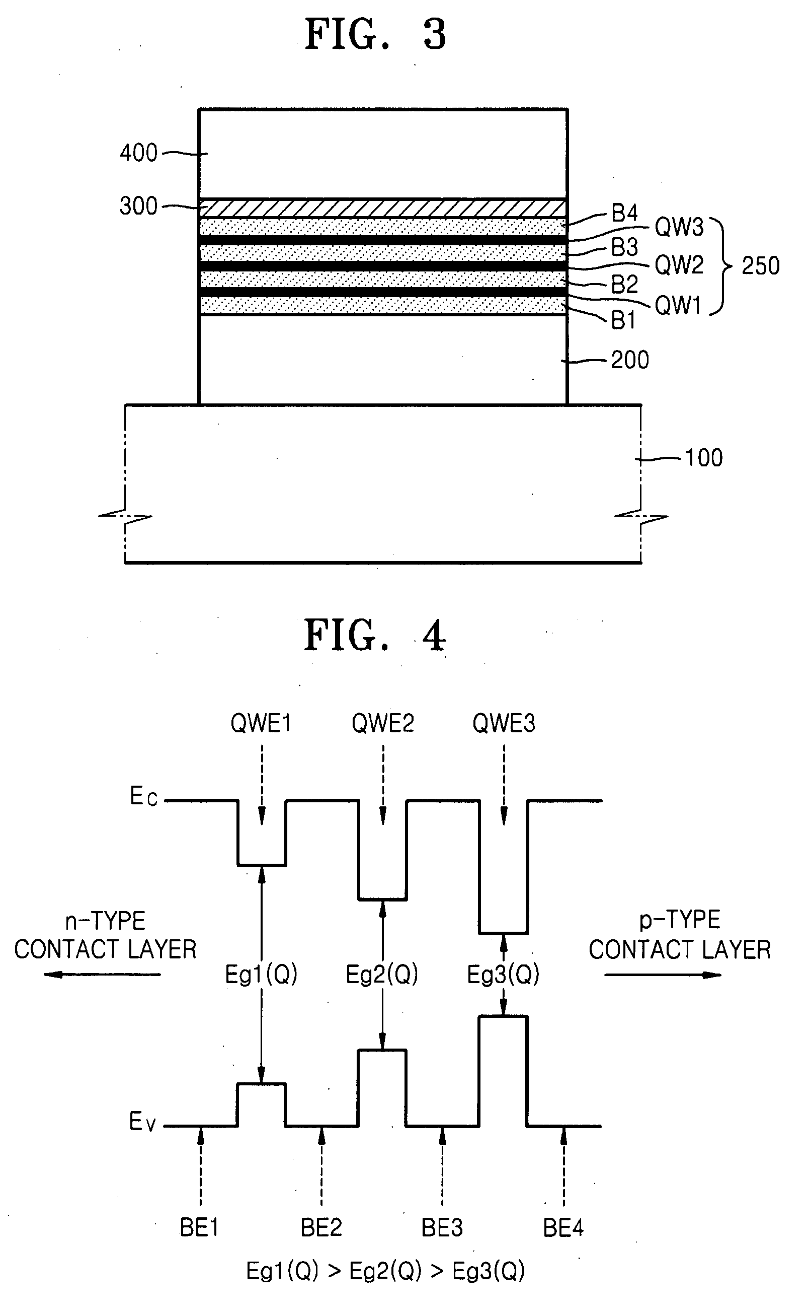
A semiconductor light emitting device may include an n-type contact layer on a substrate. An active layer may be on the n-type contact layer and/or include two or more quantum well layers and two or more barrier layers. A p-type contact layer may be on the active layer. Energy band gaps of the quantum well layers may be larger as the quantum well layers are closer to the n-type contact layer from the p-type contact layer, thicknesses of the quantum well layers may be smaller as the quantum well layers are closer to the n-type contact layer from the p-type contact layer, and/or energy band gaps of the barrier layers may be larger as the barrier layers are closer to the n-type contact layer from the p-type contact layer.

Description

PRIORITY STATEMENT[0001]This application claims the benefit of priority to Korean Patent Application No. 10-2006-0102465, filed on Oct. 20, 2006, in the Korean Intellectual Property Office, the entire contents of which are incorporated herein in their entirety by reference.BACKGROUND[0002]1. Field[0003]Example embodiments relate to a semiconductor device, and for example, to a semiconductor light emitting device in which the effect of polarization charges may be reduced.[0004]2. Description of Related Art[0005]Colors of light emitted from a light emitting diode (LED) and a laser diode (LD) vary according to a type of semiconductor compound used. A light emitting device in which a nitride-based semiconductor compound is used may emit blue or violet light.[0006]A conventional light emitting device, for example an LED or an LD, includes an active layer for changing current into light. The active layer has a structure in which at least one quantum well layer and at least one barrier lay...

Claims


Application Information

Patent Timeline
Patent Type & Authority Applications(United States)
IPC IPC(8): H01L29/02H01L33/06H01L33/32
CPCB82Y20/00H01L33/32H01L33/06
Inventor RYU, HAN-YOUL
Owner SAMSUNG ELECTRONICS CO LTD
Why Eureka
Try Eureka