Transmission-Type Display Panel and Method of Manufacturing the Same

a display panel and display panel technology, applied in the direction of identification means, instruments, manufacturing tools, etc., can solve the problems of low display brightness, increased cost, and difficulty in clearly viewing the displayed image, so as to improve display brightness and cost. low, the effect of improving the brightness

Inactive Publication Date: 2008-04-24
SUMITOMO ELECTRIC IND LTD
View PDF7 Cites 60 Cited by
  • Summary
  • Abstract
  • Description
  • Claims
  • Application Information

AI Technical Summary

Benefits of technology

[0037] According to the present invention, it is possible to fabricate a flat plate type of microlens array mechanically and thermally stable, in a simple manner and at a low cost, and then it is possible to provide a transmission-type display panel including such a microlens array and having sufficiently improved display brightness, in a simple manner and at a low cost.

Problems solved by technology

The light receiving type of display device does not emit light in itself, and thus has a problem of low display brightness that makes it difficult to clearly view the displayed image.
However, such a lens requires an increased number of fabrication processes and increase in cost, and thus an eight-level, diffraction-type lens that can cause a diffraction efficiency of 95% is sufficient in practice (this can be fabricated by repeating the above-described process N=3 times).

Method used


Image

  • Transmission-Type Display Panel and Method of Manufacturing the Same
  • Transmission-Type Display Panel and Method of Manufacturing the Same
  • Transmission-Type Display Panel and Method of Manufacturing the Same

Examples


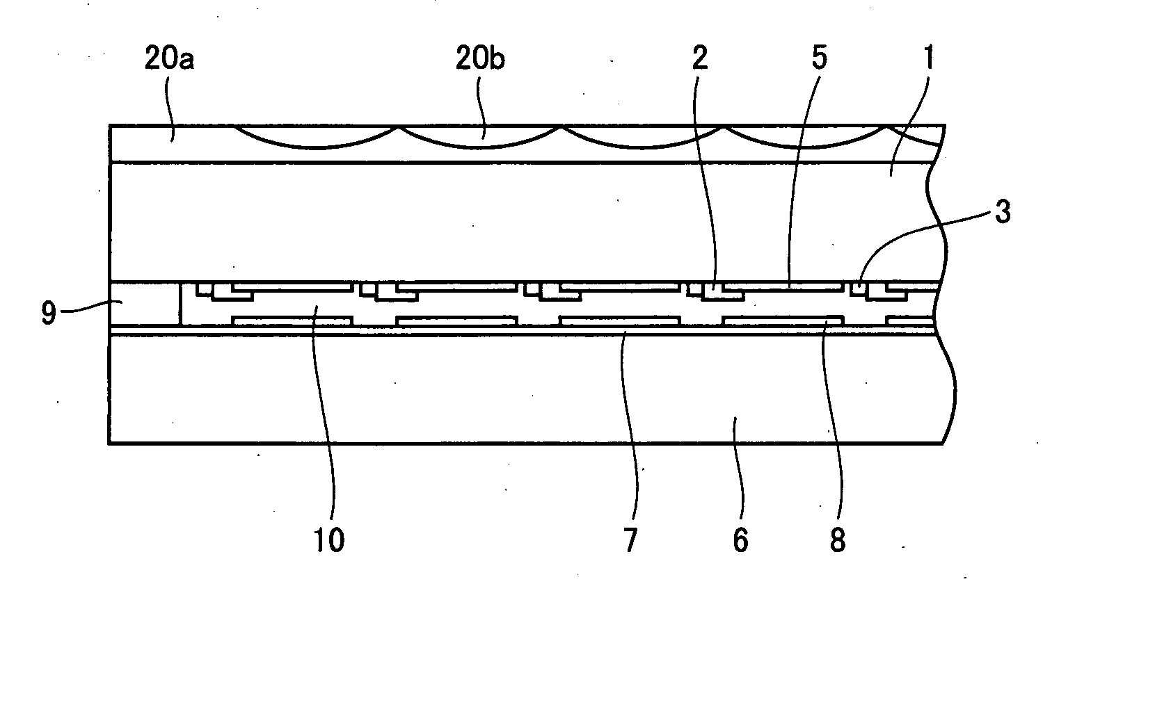
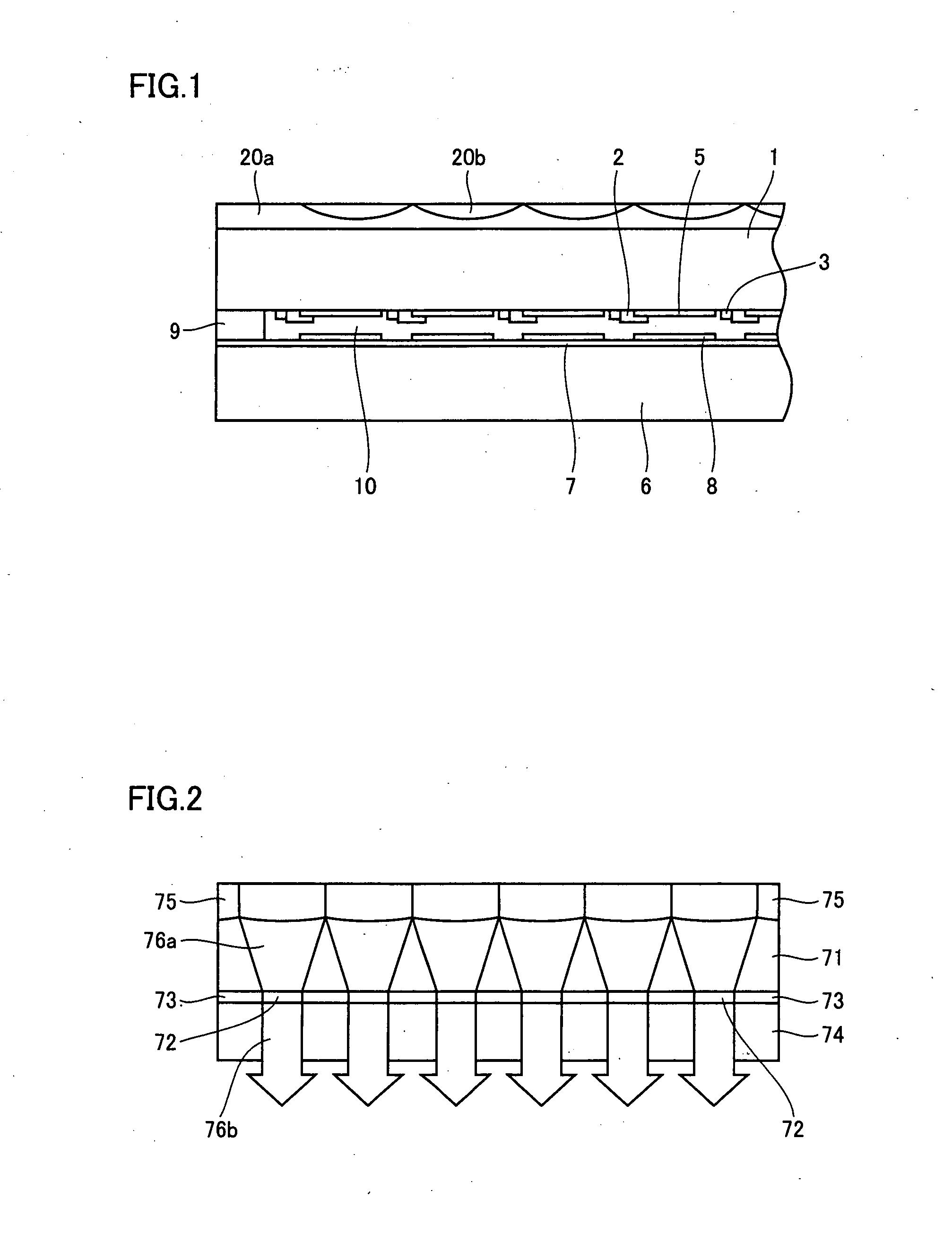
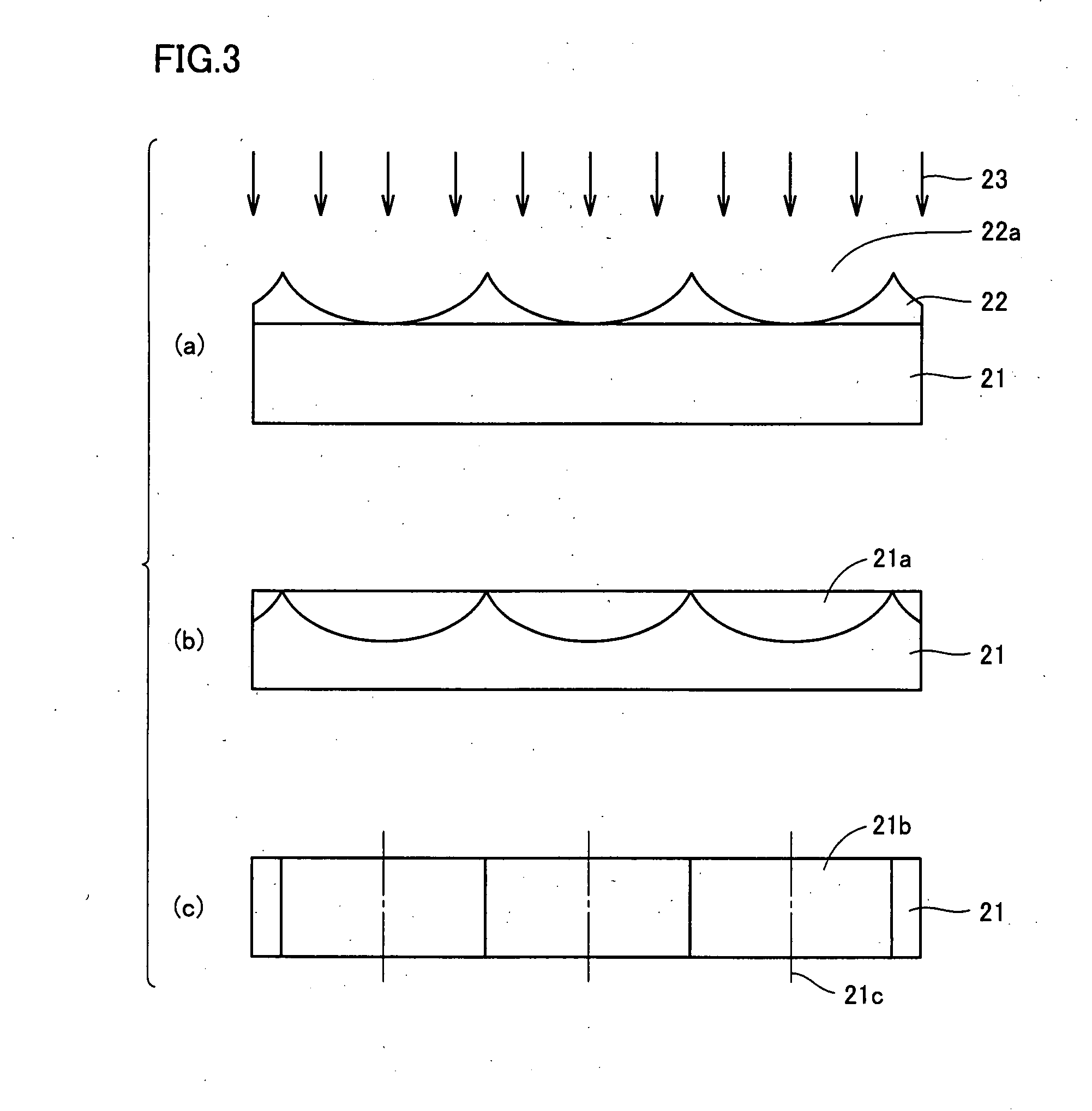
Embodiment Construction

[0052] Initially, as to formation of a microlens array required for the present invention in a transparent DLC layer, the present inventors have confirmed that the refractive index of a DLC film can be increased by application of an energy beam to the film. Such a DLC film can be formed through plasma chemical vapor deposition (CVD) on a silicon substrate, a glass substrate, a polymer substrate, or other various types of bases. The transparent DLC film obtained through such plasma CVD normally has a refractive index of approximately 1.55.

[0053] For the energy beam used for increasing the refractive index of the DLC film, it is possible to use an ultraviolet (UV) ray, an X-ray, synchrotron radiation (SR), an ion beam, an electron beam, or the like. The SR generally includes electromagnetic waves in a wide wavelength range of from ultraviolet light to an X-ray.

[0054] For example, injection of He ions at a dose rate of 5×10¹⁷ / cm2 at an acceleration voltage of 800 keV can increase the...


PUM

PropertyMeasurementUnit
refractive indexaaaaaaaaaa

Abstract

A transmission-type display panel according to the present invention includes a plurality of transparency control regions arranged in an array, a non-transparent border region existing around each of the transparency control regions, and a microlens array including a plurality of microlenses arranged in an array so as to correspond to the plurality of transparency control regions. Each of the microlenses serves to converge incident light, which is about to advance straight to the non-transparent border region, into corresponding one of the transparency control regions. The microlens array is formed by use of a transparent diamond-like carbon (DLC) film. The DLC film includes a region having its refractive index modulated corresponding to each of the microlenses, and produces a light convergence effect when light flux passes through the region having its refractive index modulated. By applying the microlens array in the DLC film to a transmission-type display panel (e.g., a liquid crystal display panel), it is possible to provide a transmission-type display panel having improved display brightness, in a simple manner and at a low cost.

Description

TECHNICAL FIELD [0001] The present invention relates to a transmission type of display panel such as a liquid crystal display panel, and particularly to improvement in display brightness of the transmission type of display panel. BACKGROUND ART [0002] Conventionally, a cathode ray tube (CRT) has mainly been used as a display device. In recent years, however, the CRT has been replaced with a flat type of display device. The flat type of display device can roughly be classified into a light emitting type and a light receiving type. As the light emitting type, there have been known a plasma display, an electroluminescent display, a light emitting diode display and others. As the light receiving type, there have been known a liquid crystal display, an electrochromic display, an electro-optic crystal display, an electrophoretic display and others. [0003] The light receiving type of display device does not emit light in itself, and thus has a problem of low display brightness that makes i...

Claims


Application Information

Patent Timeline
Patent Type & Authority Applications(United States)
IPC IPC(8): G02B27/10C03B37/018
CPCG02B3/0018G02F1/133526G02B3/0087G02B3/0031G02F1/1335G03B21/00G09F9/00
Inventor USHIRO, TOSHIHIKOODA, KAZUHIKOMATSUURA, TAKASHI
Owner SUMITOMO ELECTRIC IND LTD
Why Eureka
Try Eureka