Light-emitting diode lamp bank

a technology of light-emitting diodes and lamp banks, which is applied in the direction of semiconductor devices for light sources, fixed installations, lighting and heating apparatus, etc., can solve the problems of very small power consumption of leds, extremely low heat generated by leds, and long lifetime of led use, so as to protect strength and shear force, and enhance shear force. , the effect of not easily broken

a technology of light-emitting diodes and lamp banks, which is applied in the direction of semiconductor devices for light sources, fixed installations, lighting and heating apparatus, etc., can solve the problems of very small power consumption of leds, extremely low heat generated by leds, and long lifetime of led use, so as to protect strength and shear force, and enhance shear force. , the effect of not easily broken

US20080094828A1Inactive Publication Date: 2008-04-24SHAO SHU FA

Image

  • Light-emitting diode lamp bank
  • Light-emitting diode lamp bank
  • Light-emitting diode lamp bank

Examples


Embodiment Construction

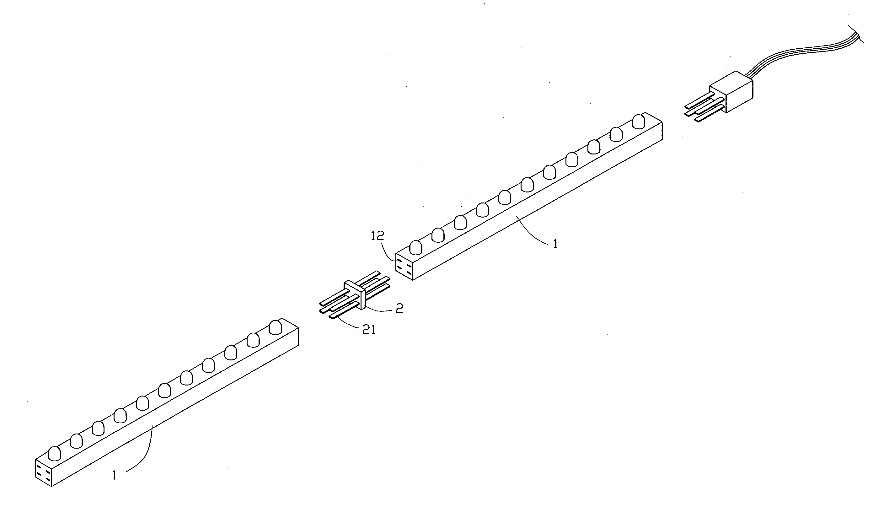
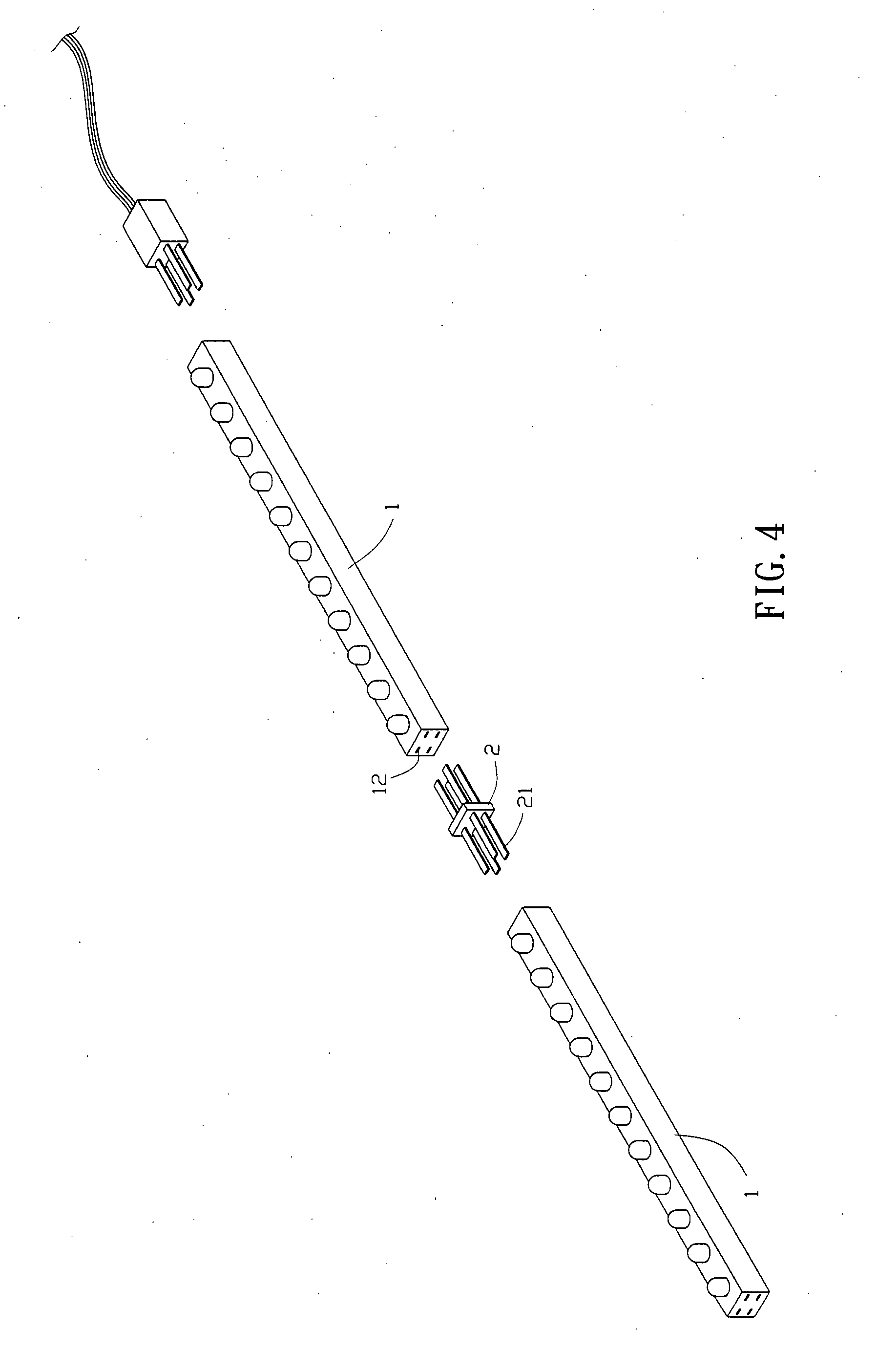
[0034]An LED (Light-Emitting Diode) lamp bank of the present invention allows an LED lamp bank 1 to connect with each other with a male connection terminal 2 to achieve effects of an easy implementation and beauty. Referring to FIG. 4, left and right end sides of the LED lamp bank 1 are provided with a same amount of female power socket holes 12 as that of the male connection terminals 2. In the drawing, there are four female seat holes 12, with each of which being provided with a positive and a negative electrode.

[0035]The male connection terminal 2 is provided with at least two-way pins 21 which can be inserted into the female socket holes 12 of the LED lamp bank 1, such that two LED lamp banks 1 can be connected serially by the two-way pins 21. Therefore, if a plurality of LED lamp banks 1 need to be connected serially, these male connection terminals 2 can be used to transmit power. By this design, in connecting the LED lamp bank 1 serially, as both ends of the bank are provided...


PUM


Abstract

An LED (Light-Emitting Diode) lamp bank is primarily formed with a plurality of LED lamps, a soft substrate, conduction wires, and soft vinyl. Two ends of each LED lamp bank are provided with female socket holes to connect with male connection terminals serially. A hard protective sheet is located at a position of the soft vinyl where each LED lamp is located, such that shear force of the soft vinyl at the location of the LED lamp can be increased, and an ill condition of fracture caused by stress concentration at the location of the LED lamp can be effectively prevented when the LED lamp bank is bended.

Description

BACKGROUND OF THE INVENTION[0001](a) Field of the Invention[0002]The present invention relates to an LED (Light-Emitting Diode) lamp bank, and more particularly to an LED lamp bank which is designed as being easily connected in serial and having large shear force, without being easily concentrated with stress, against a conventional LED lamp bank which is provided with shortcomings that it is troublesome to connect the LED lamp bank serially, that the LED lamp bank is not convenient to use, and that it is easy to cause fractures at locations of the LED lamps when the LED lamp bank is bended.[0003](b) Description of the Prior Art[0004]For an LED (Light-Emitting Diode), a principle that electric energy can be directly transformed into light energy, is used to apply voltage to terminals of positive and negative electrodes in a semiconductor, such that when electric current passes through the terminals, electrons and electron holes are combined to release the rest of energy in terms of ...

Claims


Application Information

Patent Timeline
24 Apr 2008
Publication
US20080094828A1
IPC
F21S4/00; F21S2/00; F21S8/04; F21V3/00; F21V19/00; F21V23/00; F21Y101/02; H01L33/00
CPC
F21K9/00; F21S4/003; F21V23/06; F21Y2103/003; F21Y2101/02; F21S4/20; F21Y2103/10; F21Y2115/10
Inventors
SHAO, SHU-FA