Optical in-vivo monitoring systems

a monitoring system and optical technology, applied in the field of optical devices and sensors, can solve the problems of inconvenient use of the chest strap, awkward deployment, distracting and uncomfortable wear, etc., and achieve the effects of improving the energy density of the beam, easy integration, and large surface area

Inactive Publication Date: 2008-04-24
FLORIAN JOSEPH
View PDF37 Cites 128 Cited by
  • Summary
  • Abstract
  • Description
  • Claims
  • Application Information

AI Technical Summary

Benefits of technology

[0020]Systems for in-vivo collection of modulated infra-red, IR, light are built about an ‘optical wheel’ or thin-disk system. In particular, devices are arranged in structures which can be easily integrated with a common wristwatch. An optical wheel element has an entrance aperture of very large surface area in an annular ring. An IR optical source provides illumination of a test site in tissue. The light propagating in the tissue becomes modulated in accordance with characteristics of blood flow. That radiation leaves the tissue as a result of normal scattering processes and is received by the detector at the annular aperture. The modulated light enters the optical disk at all points about the annulus, and is redirected orthogonally toward a common axial line by a complex optical element known as a circularly symmetric ‘grating’. The radiation then propagates towards and through a light pipe array which causes light to become condensed. Condensing light pipe elements of pie wedge shape further improve the energy density of the beam and further direct the beam toward a common axis which defines the axially symmetry of system components. The collected and condensed beam is further directed to a detector such as a photodiode by way of a axially symmetric conic reflector element such as a specially formed mirror.OBJECTIVES OF THESE INVENTIONS
[0021]It is a primary object of these inventions to provide systems for efficient collection of modulated light from living tissue.

Problems solved by technology

While this arrangement has the advantage of reliable detection, it is not convenient to use the chest strap which is distracting and uncomfortable to wear.
In addition, these apparatus tend to be awkward to deploy and thus lack the utility desired by consumers of these devices.
While these devices can quite accurately measure heart rate, they suffer from the inconvenience which arises from the need to apply two fingers from one hand at the wrist of the other.
Additionally, holding two fingers steady enough to permit a reliable reading while exercising is difficult.
Accordingly, these systems also present unfavorable requirements necessary to properly enable the system.
However, they do suffer from measurement interruption due to poor coupling between the photodetector and tissue.
Typically, the photodetector is quite small in size and cannot collect sufficient signal from the tissue.
They do however have the disadvantage that the display is on the wrist while the sensor is disposed about the chest via a strap.
Communication between a remote sensing device and a display systems on a wrist offer users reliability but the inconvenience of requiring the chest strap mounted sensor which is not desirable.
However, using multiple detectors increased the complexity, weight, and expense.
While these advanced systems employ sophisticated algorithms for processing return signals, they suffer because the signal collected from the tissue is weak and accompanied by significant noise.
Signals produced in-vivo are polluted with noise when a sensor is not particularly well coupled to tissue.
While systems and inventions of the art are designed to achieve particular goals and objectives, some of those being no less than remarkable, the are has limitations which prevent use of wrist worn heart rate monitors in new ways now possible.

Method used


Image

  • Optical in-vivo monitoring systems
  • Optical in-vivo monitoring systems
  • Optical in-vivo monitoring systems

Examples


Embodiment Construction

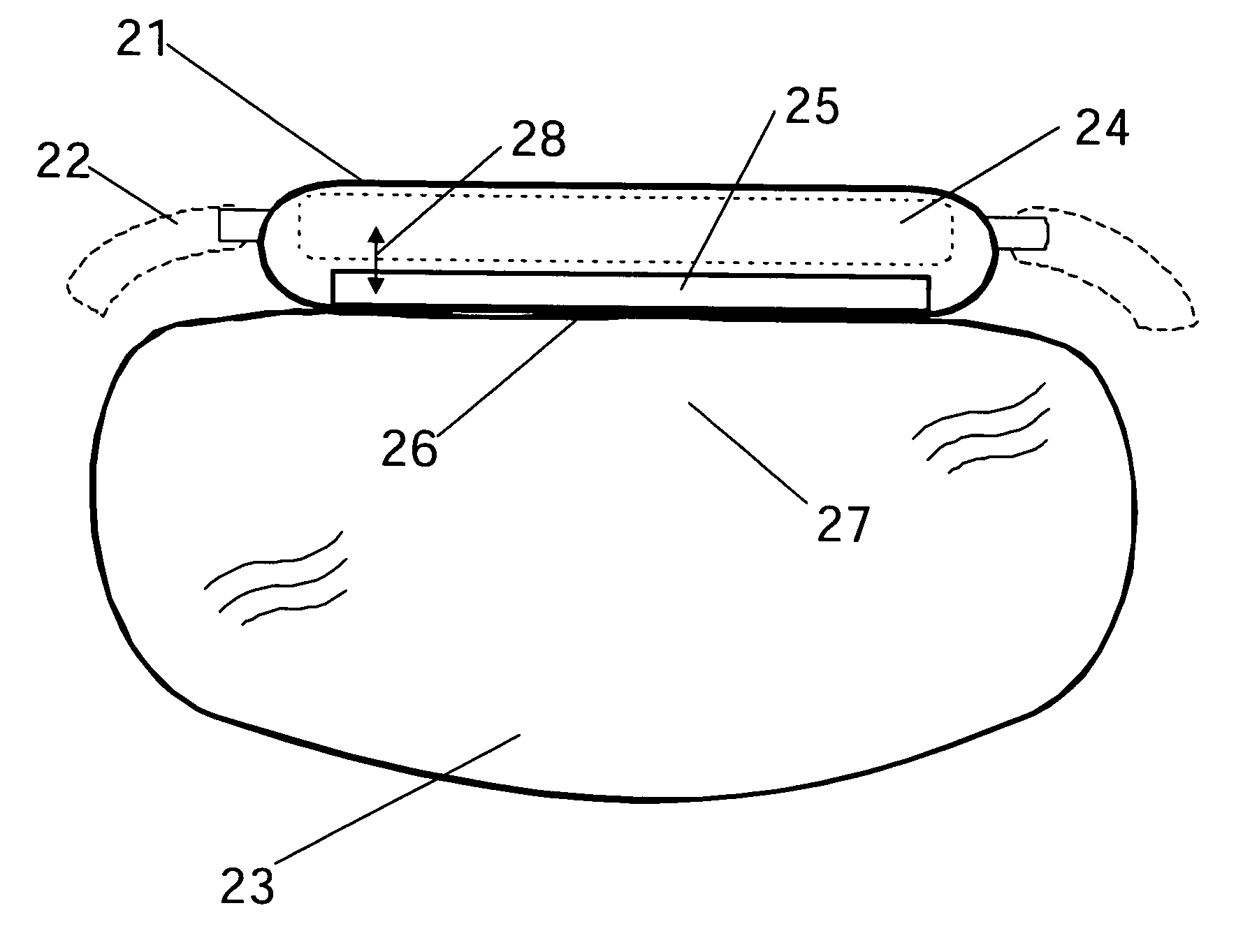
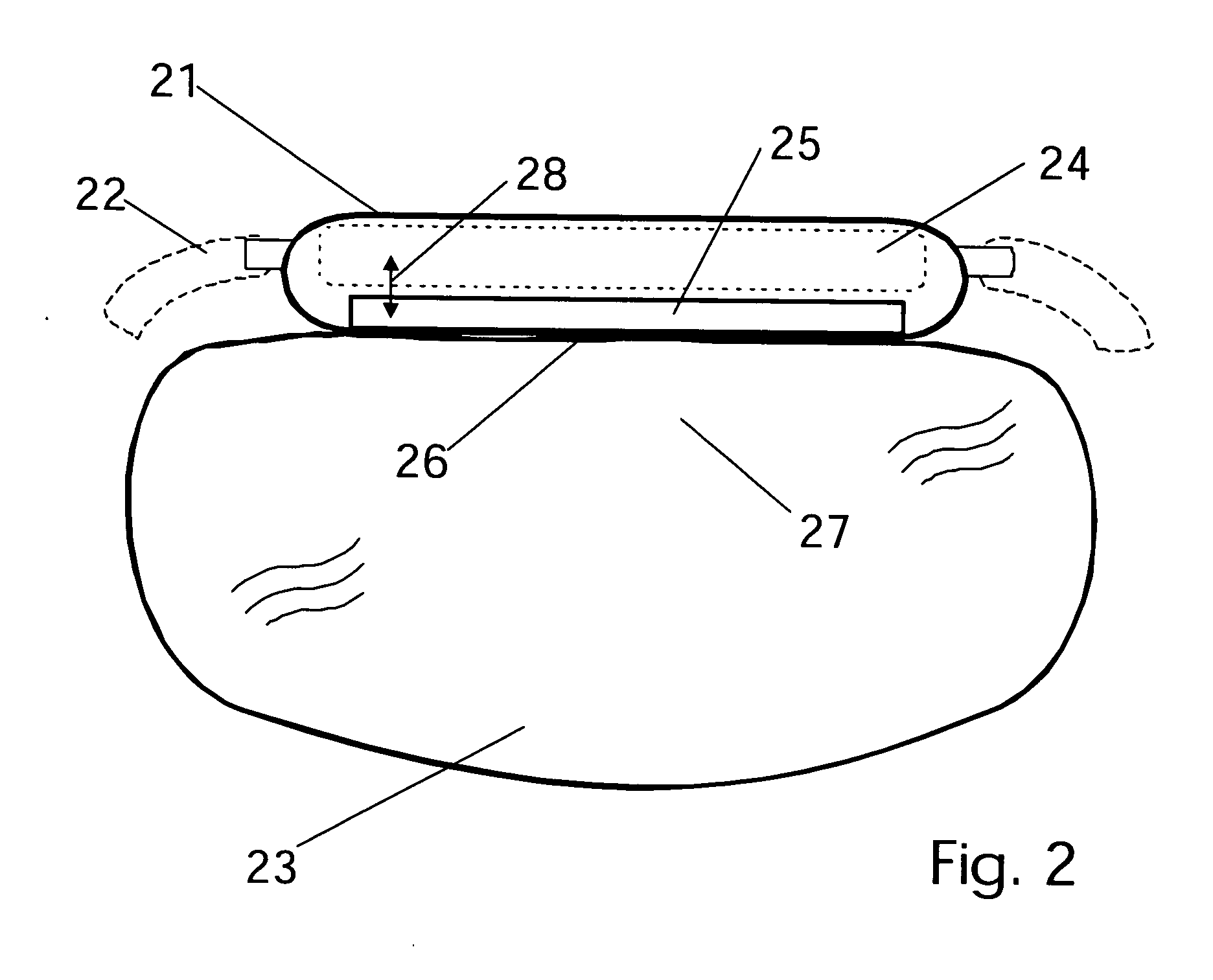
[0041]In accordance with each preferred embodiment of these inventions, there is provided apparatus for and methods of collecting modulated light from living tissue. Further, this modulated light which yields information about the state of systems under monitor is converted to an electronic signal, analyzed, and reported to a user as a real-time measure of bio activity. It will be appreciated that each of the embodiments described include both apparatus and method and further that the apparatus and method of one preferred embodiment may be different than the apparatus and method of other embodiments. The following includes an illustrative example aligned with a best mode anticipated by the inventor. While it is quite useful for illustration, it is not the only mode in which these inventions can be deployed. Rather, it is noted that systems identical to those described in the claims could be arranged in various useful applications.

[0042]In-vivo collection of modulated light from a ti...


PUM


Abstract

Systems for highly efficient, in-vivo collection of modulated infra-red light are presented. Specifically, these devices are arranged in an important format with a view to integration with a wristwatch or other wearable device. An optical aperture of large surface area, specially distributed in an annular ring, receives radiation having been modulated in a tissue test site by blood flow. Radiation received about the annular aperture is redirected by a blazed grating or similar optical element at near perpendicular angles, into a radially distributed, condensing light pipe array and further toward a common axis. Radiation converges on the axis, thus increasing the energy density of the collected signal, before it is further directed via a conic element to a detector such as a photodiode. In some versions, these highly specialized optical paths may be formed into a single element of inexpensive plastic or other rigid substrate.

Description

BACKGROUND OF THE INVENTIONS[0001]1. Field[0002]The following inventions disclosure is generally concerned with optical devices and sensors and specifically concerned with optical condensing devices and sensor systems suitable for use in conjunction with non-invasive biometric measurements.[0003]2. Prior Art[0004]Electronic heart rate monitors are sometimes used by athletes, persons practicing vigorous exercise, and advanced health practitioners, to monitor the state of their heart during various conditions. It is desirable to dynamically display heart rate information in an easily accessible location. The face of a wristwatch provides such a convenient location because a wristwatch may be comfortably worn during exercise and can be easily viewed without distraction or other interruption of the exercise.[0005]Thus, combining a heart rate monitor with a wristwatch has long been a goal of designers of advanced bio-instrumentation systems. Indeed, many systems have been developed with ...

Claims


Application Information

Patent Timeline
Patent Type & Authority Applications(United States)
IPC IPC(8): A61B6/00
CPCA61B5/02433A61B2562/146A61B5/681A61B5/14552
Inventor FLORIAN, JOSEPH
Owner FLORIAN JOSEPH
Why Eureka
Try Eureka