Non-shortening high angle wrapped balloons

Active Publication Date: 2008-04-24
WL GORE & ASSOC INC
View PDF99 Cites 83 Cited by
  • Summary
  • Abstract
  • Description
  • Claims
  • Application Information

AI Technical Summary

Benefits of technology

[0011]The balloon of the present invention is able to realize a ratio of final-to-initial overall catheter diam

Problems solved by technology

As a characteristic of wrapped balloons, it is also common to have the length of the wrapped balloon change during inflation causing placement problems during procedures.
Additionally, catheters have been unable to deliver balloons with large diameters expansion capability due to the need for a low profile and sustained high pressures.
They tend to be self-limiting as to diameter in that they will normally distend up to the rated diameter and not

Method used


Image

  • Non-shortening high angle wrapped balloons
  • Non-shortening high angle wrapped balloons
  • Non-shortening high angle wrapped balloons

Examples


example 1

Mandrel Preparation

[0057]Aluminum clamshell molds were machined with an internal balloon shape of 25 mm in diameter and 40 mm working length. The shoulders of the balloon shaped mold were tapered at an angle of 30 degrees, with respect to the mandrel axis, to a leg diameter of 2.3 mm. The axial length of the shoulder was 22.7 mm. The leg was 10 mm long. The leg stepped down to create a shutoff with a 0.914 mm diameter hypotube. A fill hole large enough to accept a syringe barrel tip was machined in the middle of the balloon working length, at the mold separation line. Appropriate vents were machined at the terminus of each leg. Before use, the mold was cleaned and lightly coated with a Lecithin based lubricant. A 0.914 mm diameter×152 mm length hypotube, PN B-HTX-20HW (Small Parts, Miami, Fla.), was lightly sandblasted to roughen the surface, and placed in the mold.

[0058]A slurry of water and Aquapour™ (Advanced Ceramics Research, Tucson, Ariz.) ceramic powder was mixed, at a ratio ...

example 2

Composite Film

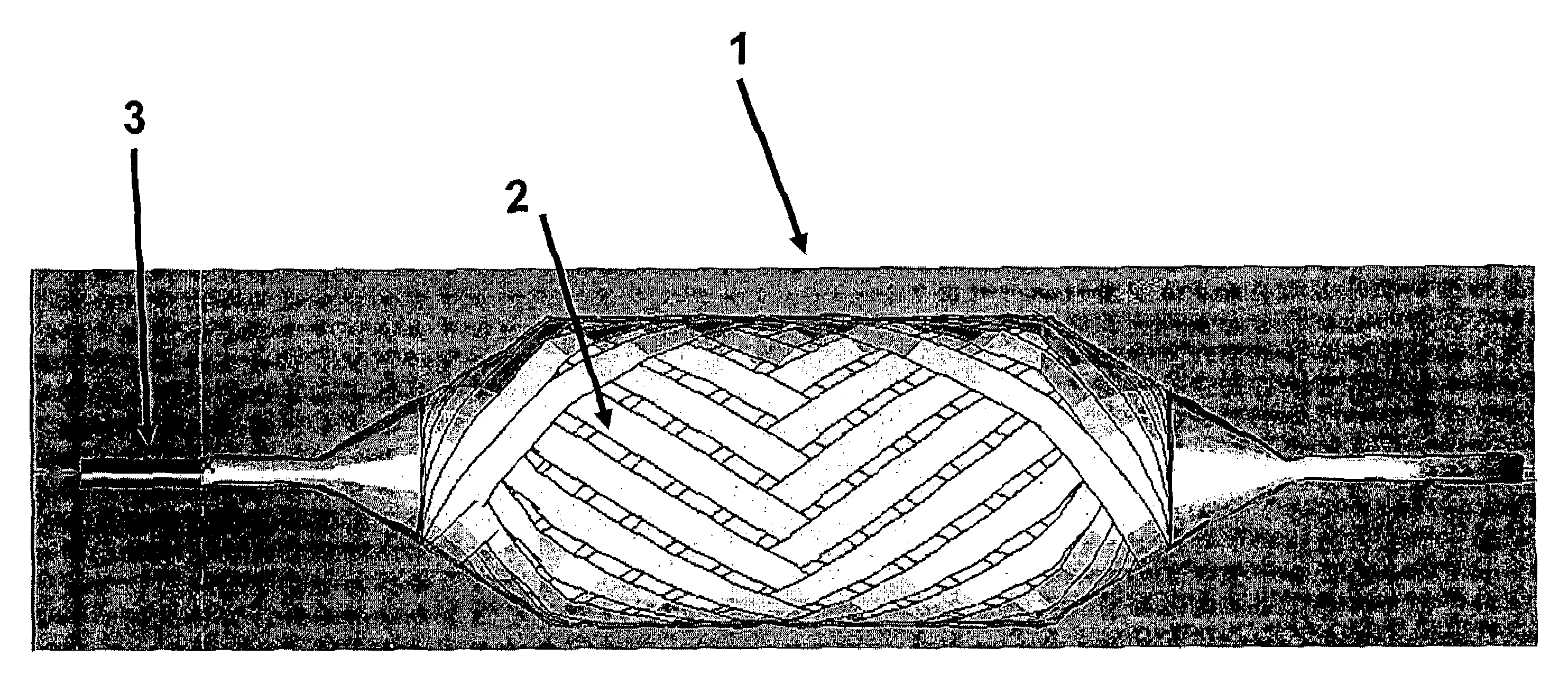
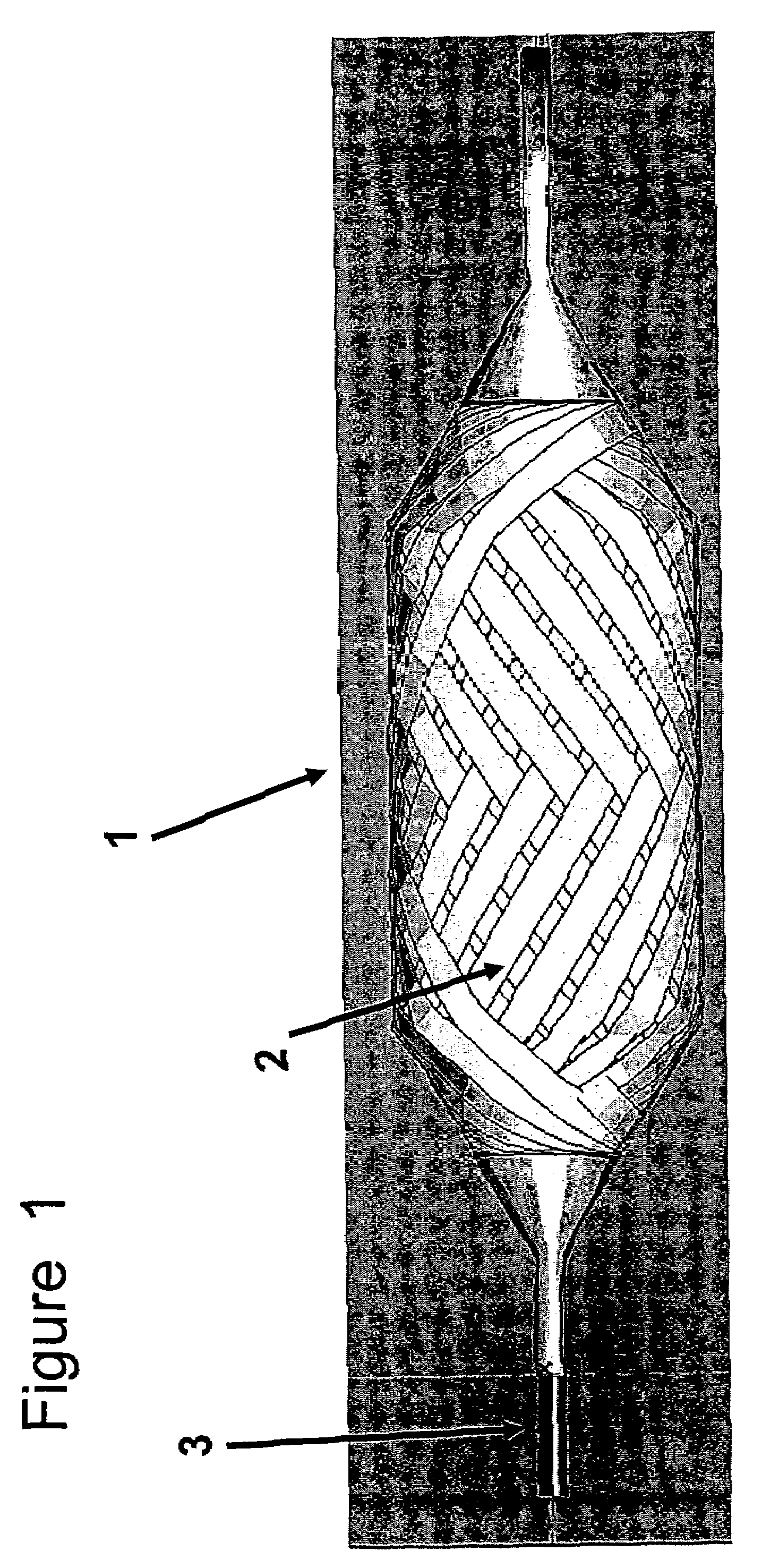
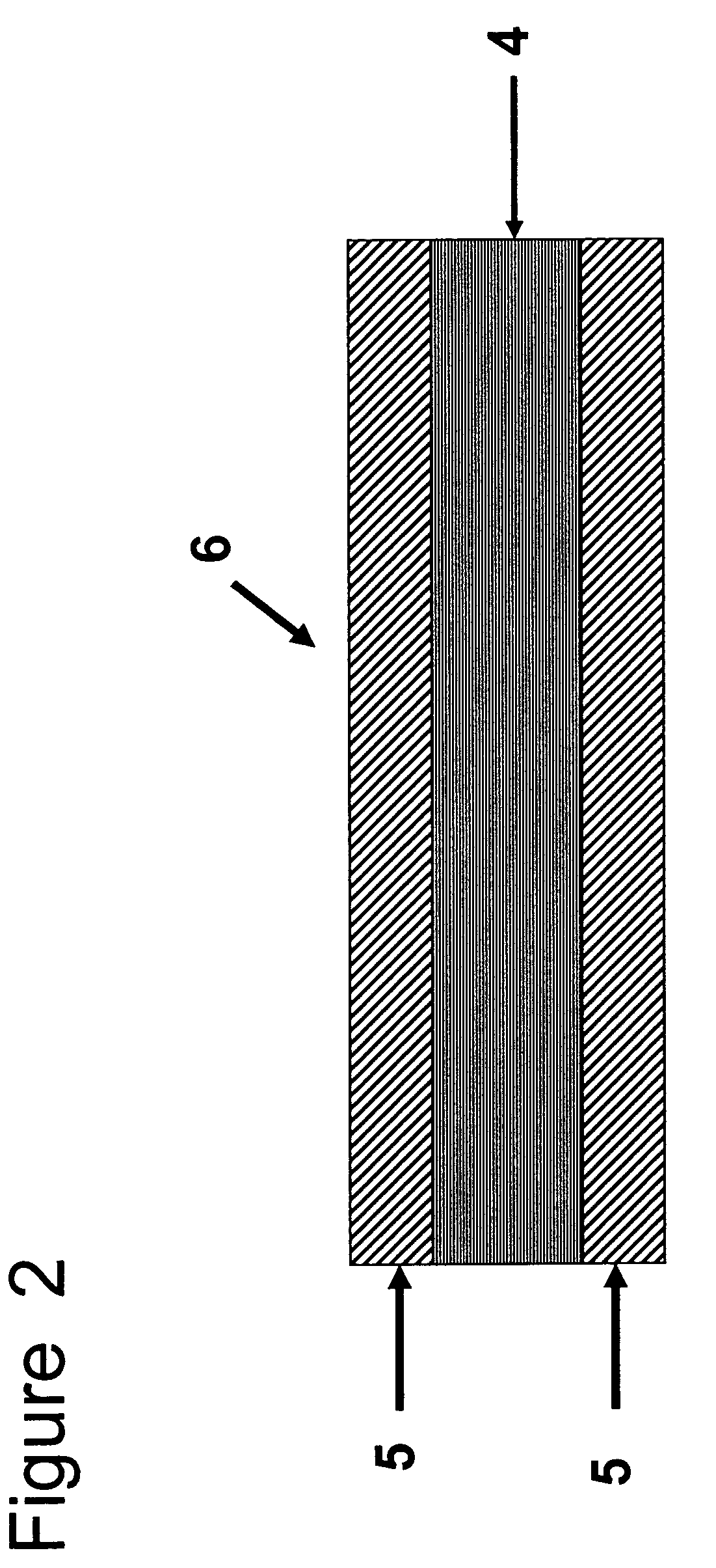
[0060]The non-distensible balloon was constructed by wrapping a composite film around the mandrel. The composite film was made by using a wire-wound rod coating process whereby a solution of Tecothane TT-1085A polyurethane and tetrahydrofuran (THF) was coated onto an ePTFE membrane. The ePTFE membrane used to make the composite film was made in accordance with the teaching in U.S. Pat. No. 5,476,589 to Bacino, incorporated herein by reference. Specifically, the ePTFE membrane was longitudinally expanded to a ratio of 55 to 1 and transversely expanded approximately 2.25 to 1, to produce a thin strong membrane with a mass of approximately 3.5 gm2 and a thickness of approximately 6.5 micrometers. A 3 percent to 8 percent by weight solution of Tecothane TT-1085A polyurethane in THF was coated onto the ePTFE membrane to produce a composite film with approximately equal amounts of Tecothane TT-1085A polyurethane on either side and throughout the ePTFE membrane and a total po...

example 3

Balloon Construction

[0061]The composite film was slit to 2.5 mm wide, and stack wound onto a 76 mm diameter core that was placed onto a payoff cart. The payoff cart angle could be adjusted to allow for different wrap configurations. Adequate tension was employed to keep the composite film taut. CADWIND NG 2005 (High End) software (Material Co., Brussels, Belgium) was utilized to develop the film wrap patterns. A variety of wrapping patterns could be used to make the non-distensible balloons of the present invention. The following wrapping layer arrangement recipe is for a 15 atmosphere burst pressure design strength non-distensible balloon:[0062]Radial[0063]Base[0064]Radial[0065]Helical 1[0066]Radial[0067]Helical 2[0068]Radial[0069]Helical 3[0070]Radial[0071]Radial[0072]Helical 1[0073]Radial[0074]Radial[0075]Helical 2[0076]Radial[0077]Radial[0078]Helical 3[0079]Radial[0080]Radial


PUM


Abstract

The present invention provides a balloon which achieves diameters greater than 6 mm for securement to a catheter. The balloon includes an elastomeric generally hollow pressure expandable body which exhibits essentially radial symmetry and constant length when expanded under an internally applied minimum working pressure from an uninflated state.

Description

BACKGROUND OF THE INVENTION[0001]The present invention relates to balloon catheters and, more particularly, to a non-shortening wrapped balloon configured to expand to a predetermined diameter upon application of a predetermined pressure thereto.[0002]Balloon catheters are well known in the art. Such catheters are employed in a variety of medical procedures, including dilation of narrowed blood vessels, placement of stents and other implants, temporary occlusion of blood vessels, and other vascular uses.[0003]In a typical application, the balloon is advanced to the desired location in the vascular system. The balloon is then pressure-expanded in accordance with a medical procedure. Thereafter, the pressure is removed from the balloon, allowing the balloon to contract and permit removal of the catheter.[0004]Procedures such as these are generally considered minimally invasive, and are often performed in a manner which minimizes disruption to the patient's body. As a result, catheters...

Claims


Application Information

Patent Timeline
IPC IPC(8): A61M25/10A61F2/958
CPCA61M25/1029A61M2025/1084A61M2025/1075A61M29/02
Inventor ALPINI, ALFRED A.HOUGHTON, MICHAELNEWCOMB, KENNETHTOWLER, JEFFREY
Owner WL GORE & ASSOC INC
Why Eureka
Try Eureka