High sensitivity microsensors based on flexure induced frequency effects

a microsensor and frequency effect technology, applied in the field of sensors, can solve the problems of insufficient sensing equipment, low system power, and prior systems that fell far short of customer requirements

Inactive Publication Date: 2008-05-01
DELAWARE CAPITAL FORMATION
View PDF18 Cites 65 Cited by
  • Summary
  • Abstract
  • Description
  • Claims
  • Application Information

AI Technical Summary

Benefits of technology

[0034]According to one embodiment, a cantilever sensor design measures flexure induced frequency change of an AWD. The sensor measures the flexure of the cantilever induced by a target matter, such as a gas, wherein the gas molecules accumulate on a sensing film affixed to only a portion of the cantilever. Bending of the cantilever is measured by the flexure-freque

Problems solved by technology

For example, it is broadly publicized that the airport and ship terminal screening measures for explosives, radioactive or biological dangers have been hampered by inadequate sensing equipment.
However, as detailed herein, these prior systems fell far short of the customer requirements in the expanding array of sensing applications.
Such a system is typically low in power and there is no pre-concentrator.
This structure may include a pre-concentrator to increase sensitivity, but takes further time to collect samples, such that they generally do not operate in real time.
This typically uses thick film polymers and subject to polymer thickness co

Method used


Image

  • High sensitivity microsensors based on flexure induced frequency effects
  • High sensitivity microsensors based on flexure induced frequency effects
  • High sensitivity microsensors based on flexure induced frequency effects

Examples


Embodiment Construction

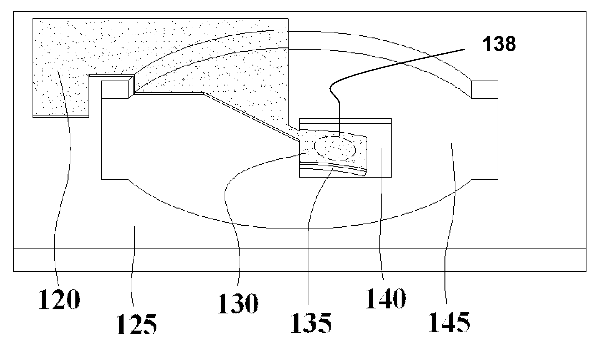
[0077]A broad objective of the present invention is to improve sensitivity of sensor technologies by employing piezoelectric cantilevers. According to one embodiment, some of the improvements are based on the cantilever's geometric response to film induced flexure / strain when exposed to a target substance.

[0078]The piezoelectric cantilever in one embodiment utilizes the fact that the resonating active acoustic wave regions of an AWD supported on or near the cantilever will respond to the flexure induced strain (and geometric change in the cantilever), caused by the increase or decrease in film stress when a sensing film along the length of the cantilever is exposed to some influence such as a target gas. The sensing film will experience an increase or decrease in internal stress causing the cantilever to bend (geometry change and strain) and this will, in turn, cause a corresponding change in frequency in the acoustically distinct AWD fabricated thereon, termed the active acoustic r...


PUM


Abstract

Acoustic sensing utilizing a cantilever structure coupled about at least one side of said cantilever to a base substrate, wherein said cantilever includes a piezoelectric section and has at least one acoustic wave device on a portion of the cantilever, wherein a flexure of the cantilever produces force-frequency effects measurable by the acoustic wave device. According to one embodiment, the cantilever sensor uses the flexure-frequency effect as measured by an acoustic wave device to sense a target matter. According to one embodiment, a sensing material is disposed on at least a portion of at least one surface of the cantilever.

Description

RELATED APPLICATIONS[0001]This application claims the benefit of U.S. Provisional Applications No. 60 / 863,871, filed Nov. 1, 2006, and is herein incorporated in its entirety by reference.FIELD OF THE INVENTION[0002]The invention relates to sensors, and more particularly, to sensing technology involving cantilevers.BACKGROUND OF THE INVENTION[0003]There have been significant advances in the sensing industry based on requirements for such fields as airport security as well as military and medical applications. For example, it is broadly publicized that the airport and ship terminal screening measures for explosives, radioactive or biological dangers have been hampered by inadequate sensing equipment.[0004]There are various types of sensors and sensing applications. Current gas sensors are typically based on mass loading of a sensing film upon exposure to a target analyte. Mass loading refers to measuring changes of the vibrating member due to on an increase of the mass caused by an ad...

Claims


Application Information

Patent Timeline
IPC IPC(8): H01L41/04G01H3/06
CPCG01H11/08H01L41/1132G01N29/022H10N30/302
Inventor HASKELL, REICHL B.STEVENS, DANIEL S.ANDLE, JEFFREY C.
Owner DELAWARE CAPITAL FORMATION
Why Eureka
Try Eureka