
Wireless communication system, wireless communication apparatus, wireless communication method, and computer program

a wireless communication system and wireless communication technology, applied in the field of wireless communication systems, wireless communication apparatuses, wireless communication methods, computer programs, can solve the problems of increasing overall system power consumption, time consuming, and reducing the efficiency of detecting radar waves, so as to prevent radar wave interference with increased certainty, reduce the average power consumption of communication stations, and efficiently detect radar waves

Inactive Publication Date: 2008-05-01
SONY CORP
View PDF9 Cites 37 Cited by
  • Summary
  • Abstract
  • Description
  • Claims
  • Application Information

AI Technical Summary

Benefits of technology

This approach reduces the average power consumption of communication stations, extends device operating time, and prevents radar wave interference by ensuring continuous radar wave detection without overburdening any single station, thus maintaining system throughput and user-friendliness.

Problems solved by technology

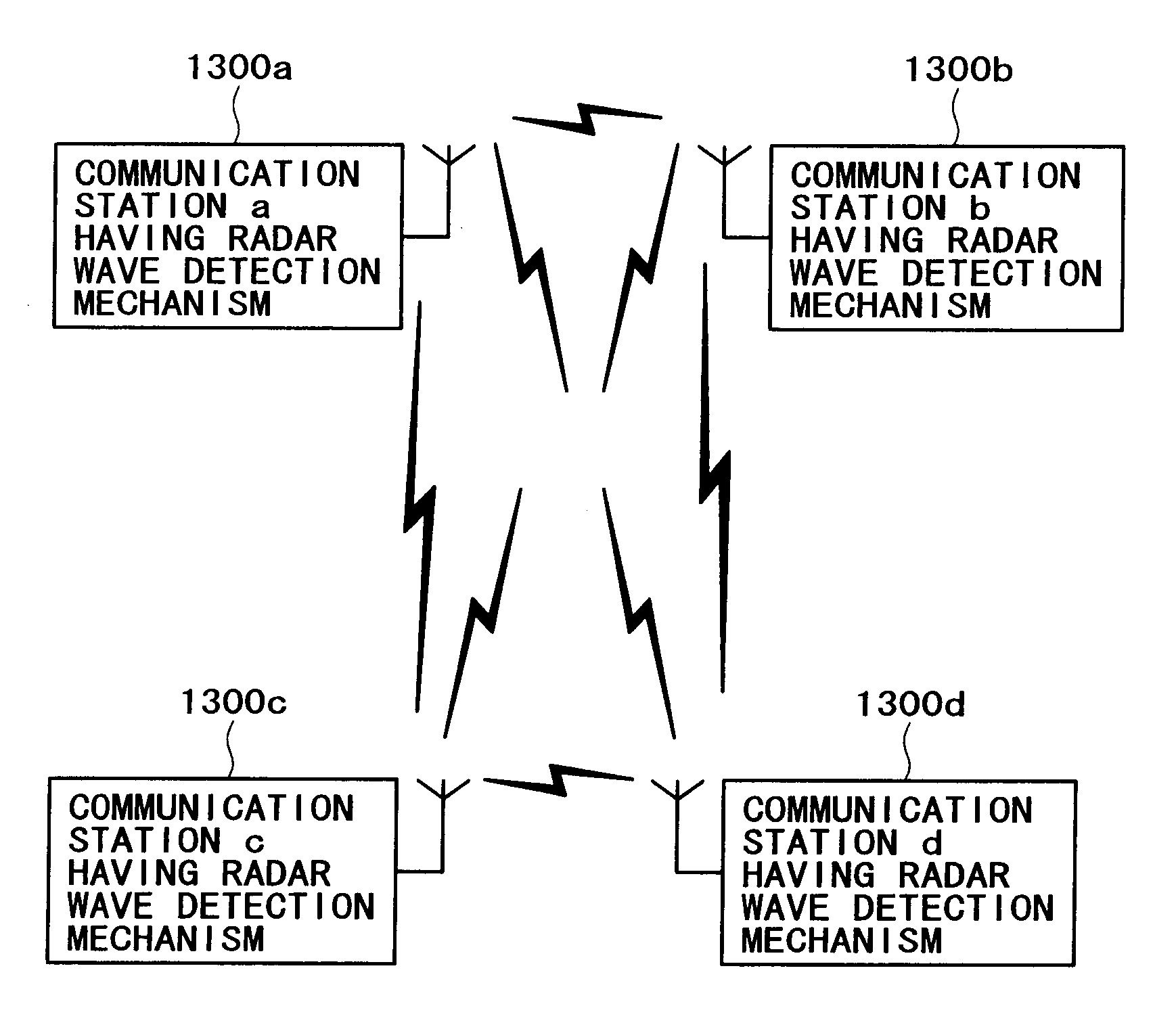
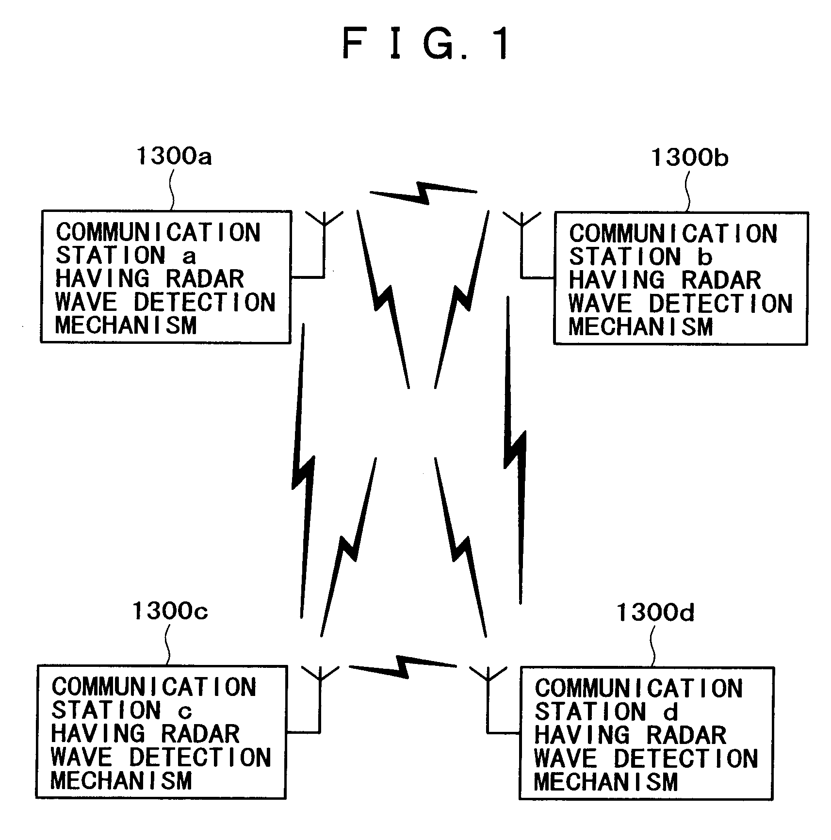
In a system comprising an access point and a plurality of mobile stations, for instance, a “hidden base station” problem may arise so that a radar wave reaches the mobile stations but does not reach the access point.
However, no radar wave detection / interference avoidance technology has been developed for use in such an ad-hoc wireless communication system.
Therefore, the overall system power consumption increases.
At a battery-powered mobile station, for instance, the operating time decreases due to power consumption for radar wave detection so that the degree of user-friendliness decreases.
However, such an increase in the battery capacity goes against the trend toward reducing the device size, weight, and price.

Method used


Image

  • Wireless communication system, wireless communication apparatus, wireless communication method, and computer program
  • Wireless communication system, wireless communication apparatus, wireless communication method, and computer program
  • Wireless communication system, wireless communication apparatus, wireless communication method, and computer program

Examples


Embodiment Construction

[0085] Embodiments of the present invention will now be described with reference to the accompanying drawings.

[0086] The present invention assumes that a wireless communication path is used to establish a network among a plurality of communication stations. The present invention also assumes that store-and-forward traffic is used for communication, and that information is transferred in packets. Although the following explanation assumes that each communication station uses a single channel, the present invention can also be applied to a case where a multi-channel transmission medium is used to handle a plurality of frequency channels.

[0087] In a wireless network according to the present invention, transmission (MAC) frames having a moderate time-division multiple access structure are used to exercise transmission control while effectively using a channel resource. Each communication station can transmit information directly and asynchronously by performing an access procedure bas...


PUM


Abstract

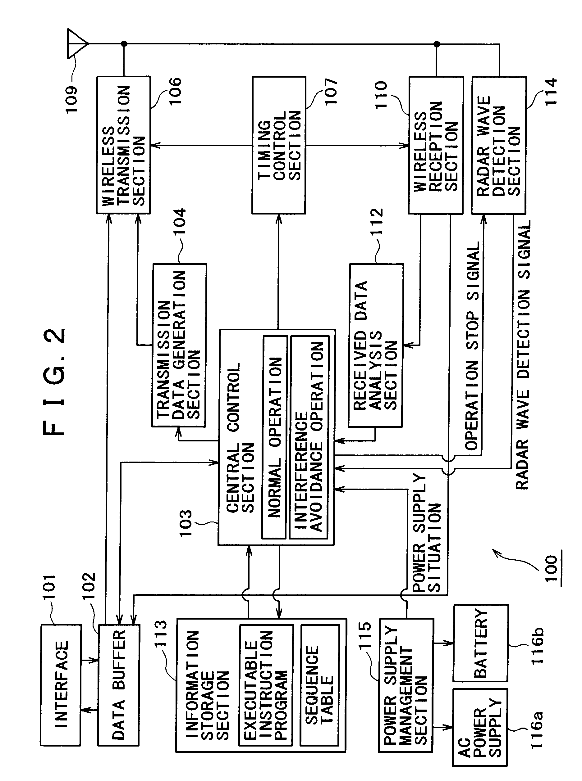
Disclosed is radar wave detection and DFS (dynamic frequency selection) with high efficiency while considering, for instance, the power consumption of each communication station within an autonomous distributed network. At least one communication station runs in an interference avoidance operation mode, operates a radar wave detection section, and fulfills the obligation to issue instructions for radar wave detection and DFS for an approximately predetermined period of time. After the lapse of the approximately predetermined period of time, another communication station switches to the interference avoidance operation mode and assumes the obligation to issue instructions for radar wave detection and DFS. In other words, two or more communication stations sequentially run in the interference avoidance operation mode in a time sharing manner. Therefore, the average power consumption of the communication stations decreases.

Description

CROSS-REFERENCE TO RELATED APPLICATIONS [0001] This application is a continuation of U.S. application Ser. No. 11 / 037,107, filed Jan. 19, 2005, and is based upon and claims benefit of priority from Japanese Patent Application No. 2004-032737. filed Feb. 9, 2004, the entire contents of each of which is incorporated by reference.BACKGROUND OF THE INVENTION [0002] The present invention relates to a wireless communication system, wireless communication apparatus, wireless communication method, and computer program for establishing communication among a plurality of wireless stations that constitute, for instance, a wireless LAN (Local Area Network), and more particularly to a wireless communication system, wireless communication apparatus, wireless communication method, and computer program for allowing various communication stations to perform network operations in an autonomous distributed manner without using any specially installed control station. [0003] More specifically, the pres...

Claims


Application Information

Patent Timeline
Patent Type & Authority Applications(United States)
IPC IPC(8): H04K3/00H04B1/10H04B1/40H04L12/28H04W16/14H04W16/16H04W48/16H04W52/02H04W74/08H04W84/12H04W84/18H04W88/02
CPCG01S7/021H04K2203/18H04B1/401H04W16/14H04W16/16H04W48/16H04W84/12H04W84/18H04W88/02H04W88/021H04W52/0238Y02B60/50H04K3/226H04K3/822H04B1/1027Y02D30/70
Inventor YAMAURA, TOMOYA
Owner SONY CORP
Learn More