Key Distribution in Systems for Selective Access to Information

a technology of information and key management, applied in the field of key management in systems for selective access to information, can solve the problems of increasing both computational cost and bandwidth consumption, system is state-full or state-dependent, and the participant is able to easily re-catch the session, so as to reduce the size of the key management message directed, reduce the size of the group key management message, and achieve acceptable security level

Inactive Publication Date: 2008-05-01
TELEFON AB LM ERICSSON (PUBL)
View PDF3 Cites 37 Cited by
  • Summary
  • Abstract
  • Description
  • Claims
  • Application Information

AI Technical Summary

Benefits of technology

[0023]Another object is to significantly reduce the size of a group key management message while maintaining an acceptable security level.
[0024]It is an object to optimize the creation of subsets of users thereby reducing the size of a key management message directed to the subset of users.
[0025]I

Problems solved by technology

The main problem with key-distribution is to update the MDP-key as fast as possible when new users either join or leave the group in a way, which is scalable to large groups.
The naive approach of sending the updated MDP-key encrypted individually for each user does not scale well and it is resource consuming, increasing both computational cost and bandwidth consumption.
A possible drawback is that the system is state-full or state-dependent, i.e. the algorithm makes use of the previous group key to encrypt the new generated group key.
In the case the group key for a certain state is lost it is not possible for the participant to easily re-catch the session by any means.
Another drawback is that a provided method for batch re-keying, i.e. batch update of keys, is not very efficient in particular at times of major and momentary changes of user status.
The size of a key management message tends to become very large in large groups.
Because of the size of a key management message it would be very resource consuming to frequently multicast or broadcast such me

Method used


Image

  • Key Distribution in Systems for Selective Access to Information
  • Key Distribution in Systems for Selective Access to Information
  • Key Distribution in Systems for Selective Access to Information

Examples


first embodiment

[0115] a normal tree is created in the first step and all users without state key are marked as active users of the group. By doing so it will then be easy to calculate, in the second step, the subsets using a general cover method. To see this, consider FIG. 5B where leaves 8, 9, 10, 13, and 15 have the state key tree, and leaves 11, 12, and 14 do not have the state key. According to the first step, leaves 11, 12, and 14 are marked as active. In FIG. 5B leaves are shown shadowed to remind that they do not have the current state. If we want to revoke leaves 13, and 15 (marked with a cross in FIG. 5B), the general algorithm would have created the sets S1,3 to cover all leaves in the left branch of the root, S6,13 to cover leaf 12, and S7,15 to cover leaf 14. A key update message of the form Eq. 4 or Eq.4′ is used. It is then noticed that leaves 11, 12, and 14 although covered by the sets specified above still will not be able to retrieve the new key as these leaves do not have the cur...

third embodiment

[0118] said first mark-up step, comprises marking the leaves according to the following rules:[0119]All leaves without state key are marked undefined.[0120]All leaves with state key are either marked user or not user as is the case.

[0121]In FIG. 5C the undefined leaves are marked with lines and leaves with a state key are marked with dots. Further, in FIG. 5C, leaves 13 and 15 are cross-marked to indicate that these leaves shall not be users.

[0122]Said second combined marking and calculation step comprises the following algorithm applied to a tree as illustrated in FIG. 5C:[0123]For each level in the tree, starting from the leaves, go one level up in the tree and for each node at that level do the steps:[0124]a. If both the left and right child are marked as undefined, mark the node as undefined,[0125]b. If one child, denoted x, is marked as undefined but the other child, denoted y, is either marked user or not user then mark the node as y and mark all leaves under x as y,[0126]c. I...

fifth embodiment

[0130] a more efficient method of creating the subset covering is disclosed that leads to an optimal cover. This method is based on a coloring algorithm where nodes are given different colors depending on the status of the node. According to this embodiment, said first step involves coloring the leaves. A leaf is colored “red” if it shall be revoked in the current update process, i.e. it belongs to the set UR. A leaf is colored “black” if it is already revoked and does not have the current state key, i.e. it belongs to the set U0. Finally, a leaf is colored “blue” if it shall remain user of the group in the current update i.e. it belongs to the set UA. It follows that leaves can only have one of these colors.

[0131]Thereafter the combined marking and calculation second step is performed. The marking proceeds according to the following rules. Nodes are colored that are above the bottom level. The colors of the children are basically “added” to make up the color of the parent. If at le...


PUM


Abstract

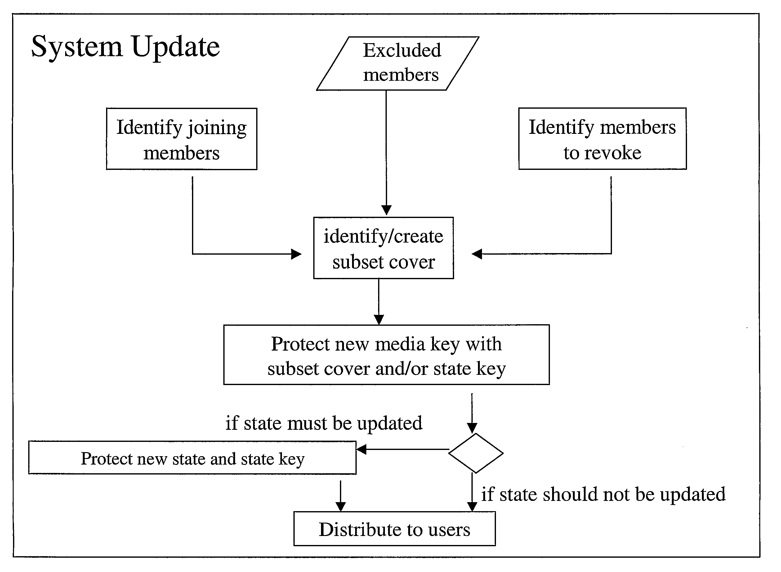
A combination of stateless and state-full techniques enable reduced overall key management messages. A set of encryption keys is created based on a stateless subset cover scheme, where each user is associated with a leaf in the subset cover scheme. A state key and a corresponding state representing a subset of users that have the state key and a subset of users that do not have the state key is established, and a subset cover based on information representative of the established state is determined. Finally, a group key management message can be determined at least partly based on the calculated subset cover. The introduced state opens up for efficient subset cover calculation, reducing the size of the key management message.

Description

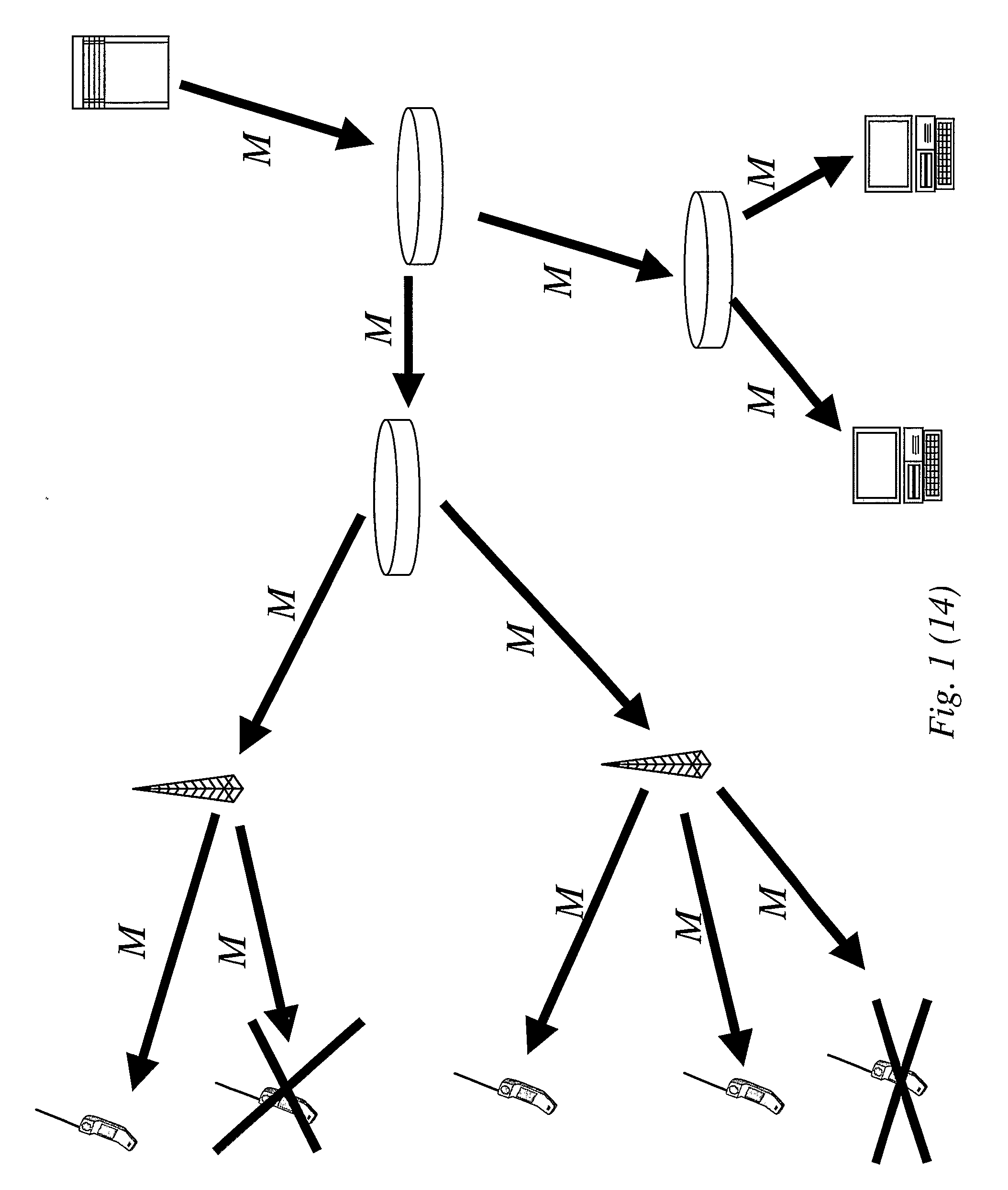
TECHNICAL FIELD OF THE INVENTION[0001]The present invention generally relates to key management in systems for selective access to information, and more specifically to distribution of key messages for derivation of a media key or equivalent for decoding e.g. secure broadcast, as well as optimization of such key messages.BACKGROUND OF THE INVENTION[0002]Key management is of crucial importance in any system for selective access to information, such as broadcast or multicast protection systems. Broadcast and multicast enables efficient distribution of protected information to large groups of receivers, as schematically illustrated in FIG. 1, for both wireless applications and standard data communications. In the following the term broadcast will be used to refer to both broadcast and multicast. Recent efforts focus on broadcast over wireless networks and a key topic is to use the wireless link as efficiently as possible, for example to reduce time for media access. Another topic of ke...

Claims


Application Information

Patent Timeline
IPC IPC(8): H04L9/08H04L9/40
CPCH04L9/0836H04L63/065H04L9/0891
Inventor LINDHOLM, FREDRIKKREITZ, GUNNAR
Owner TELEFON AB LM ERICSSON (PUBL)
Why Eureka
Try Eureka