
Vortex chamber lids for atomic layer deposition

a technology of atomic layer and vacuum chamber lid, which is applied in the direction of chemical vapor deposition coating, coating, coating process, etc., can solve the problems of large amount of ongoing effort and difficulty in deposition process filling submicron structure, and achieve the effect of reducing the velocity of gas

Inactive Publication Date: 2008-05-01
APPLIED MATERIALS INC
View PDF41 Cites 405 Cited by
  • Summary
  • Abstract
  • Description
  • Claims
  • Application Information

AI Technical Summary

Benefits of technology

[0032] In another embodiment, a method for depositing a material layer over a substrate structure is provided which includes delivering gases to a substrate in a substrate processing chamber contains providing one or more gases into the substrate processing chamber, reducing a velocity of the gases through non-adiabatic expansion, providing the gases to a central portion of the substrate, and directing the gases radially across the substrate from the central portion of the substrate to a peripheral portion of the substrate.

Problems solved by technology

However, as the fringes of circuit technology are pressed, the shrinking dimensions of interconnects in VLSI and ULSI technology have placed additional demands on the processing capabilities.
Many traditional deposition processes have difficulty filling submicron structures where the aspect ratio exceeds 4:1, and particularly where the aspect ratio exceeds 10:1.
Therefore, there is a great amount of ongoing effort being directed at the formation of substantially void-free and seam-free submicron features having high aspect ratios.

Method used


Image

  • Vortex chamber lids for atomic layer deposition
  • Vortex chamber lids for atomic layer deposition
  • Vortex chamber lids for atomic layer deposition

Examples


Embodiment Construction

[0053] Embodiments of the invention provide apparatuses and methods that may be used to deposit materials during an atomic layer deposition (ALD) process. Embodiments include ALD process chambers and gas delivery systems which contain an expanding channel lid assembly, a converge-diverge lid assembly, a multiple injection lid assembly, or an extended cap lid assembly. Other embodiments provide methods for depositing materials using these gas delivery systems during ALD processes.

Expanding Channel Lid Assembly

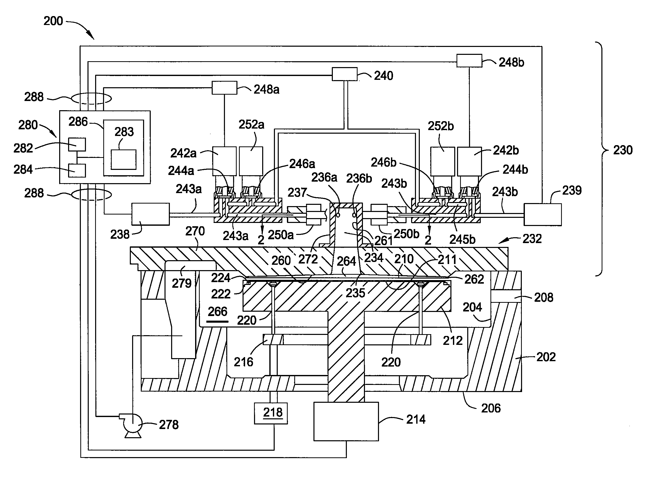
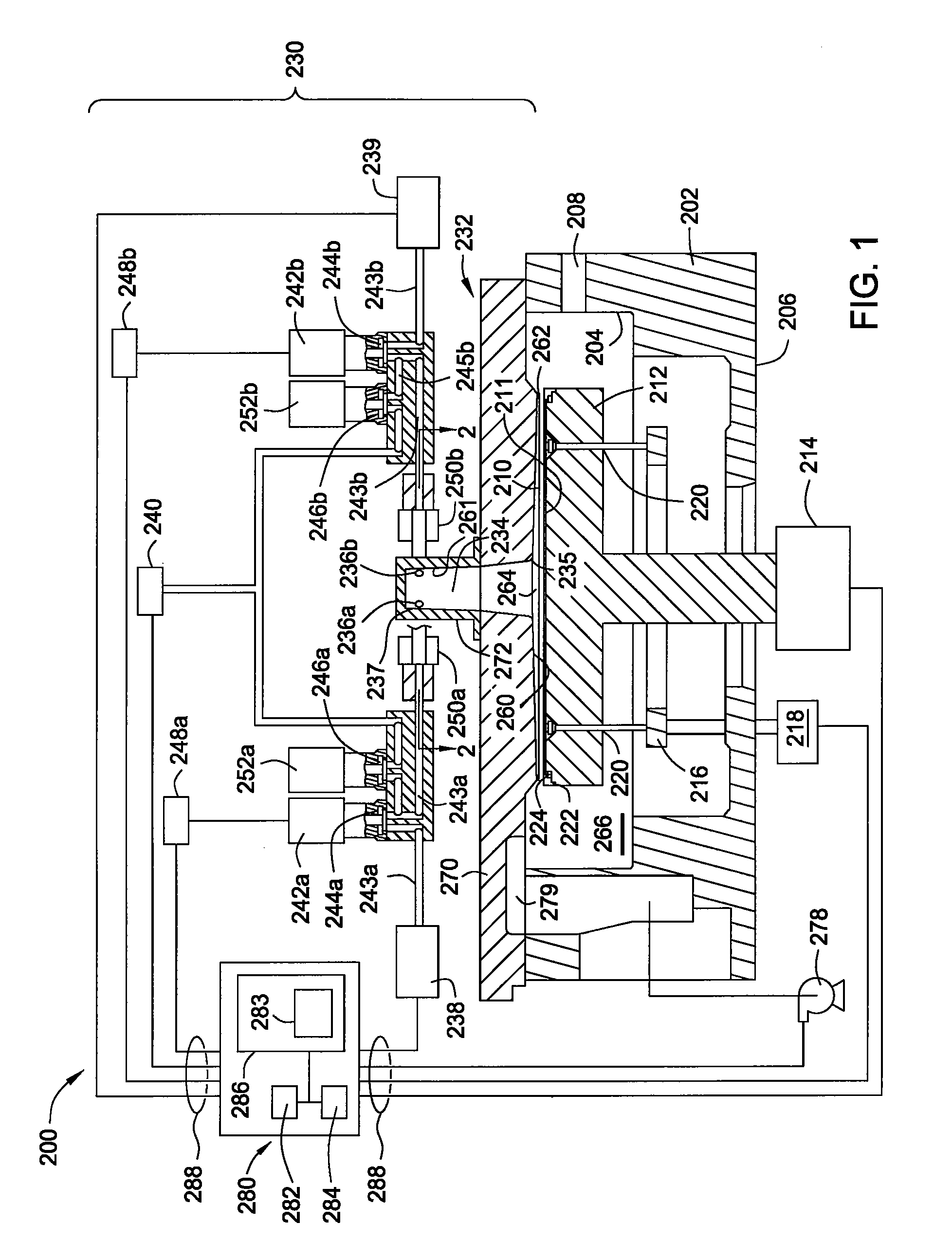
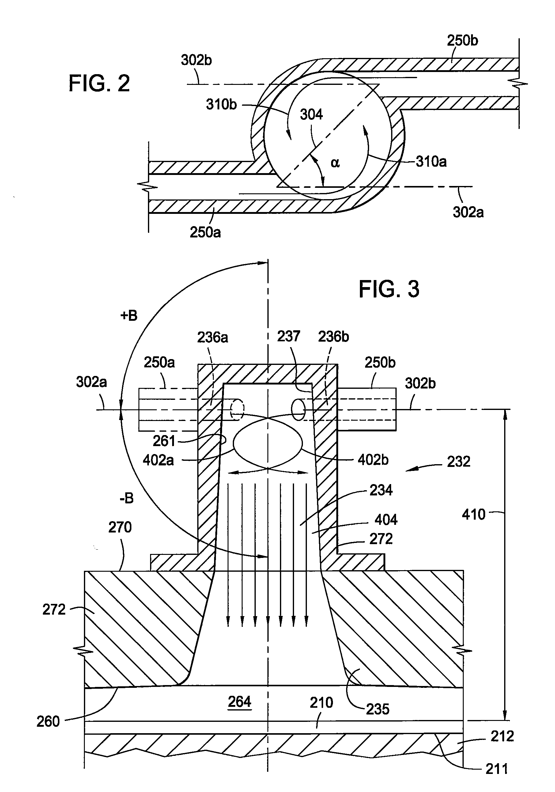
[0054]FIG. 1 is a schematic cross-sectional view of one embodiment of process chamber 200 including gas delivery system 230 adapted for ALD or sequential layer deposition. Process chamber 200 contains a chamber body 202 having sidewalls 204 and bottom 206. Slit valve 208 in process chamber 200 provides access for a robot (not shown) to deliver and retrieve substrate 210, such as a 200 mm or 300 mm semiconductor wafer or a glass substrate, to and from process chamber 200.

[005...


PUM

PropertyMeasurementUnit
Timeaaaaaaaaaa
Timeaaaaaaaaaa
Timeaaaaaaaaaa

Abstract

Embodiments of the invention relate to apparatuses and methods for depositing materials on substrates during atomic layer deposition processes. In one embodiment, a chamber for processing substrates is provided which includes a chamber lid assembly containing an expanding channel at a central portion of the chamber lid assembly, wherein an upper portion of the expanding channel extends substantially parallel along a central axis of the expanding channel, and an expanding portion of the expanding channel tapers away from the central axis. The chamber lid assembly further contains a conduit coupled to a gas inlet, another conduit coupled to another gas inlet, and both gas inlets are positioned to provide a circular gas flow through the expanding channel. In one example, the inner surface within the upper portion of the expanding channel has a lower mean surface roughness than the inner surface within the expanding portion of the expanding channel.

Description

CROSS-REFERENCE TO RELATED APPLICATIONS [0001] This application claims benefit of U.S. Ser. No. 60 / 862,764 (APPM / 011546L), filed Oct. 24, 2006, which is herein incorporated by reference in its entirety. [0002] This application is also a continuation-in-part of U.S. Ser. No. 11 / 077,753 (APPM / 005192.C1), filed Mar. 11, 2005, which is a continuation of U.S. Ser. No. 10 / 032,284 (APPM / 005192.02), filed Dec. 21, 2001, and issued as U.S. Pat. No. 6,916,398, which claims benefit of U.S. Ser. No. 60 / 346,086 (APPM / 005192L), filed Oct. 26, 2001, which are herein incorporated by reference in their entirety. [0003] This application is also a continuation-in-part of U.S. Ser. No. 11 / 680,995 (APPM / 006766.C1), filed Mar. 1, 2007, which is a continuation of U.S. Ser. No. 10 / 712,690 (APPM / 006766), filed Nov. 13, 2003, and issued as U.S. Pat. No. 7,204,886, which claims benefit of U.S. Ser. No. 60 / 426,134 (APPM / 006766L), filed Nov. 14, 2002, which are herein incorporated by reference in their entirety...

Claims


Application Information

Patent Timeline
IPC IPC(8): C23C16/44
CPCC23C16/34H01L21/76871C23C16/4411C23C16/4412C23C16/45502C23C16/45504C23C16/45508C23C16/45512C23C16/45525C23C16/45544C23C16/45563C23C16/45582H01L21/28562H01L21/76843H01L21/76846C23C16/4404
Inventor WU, DIEN-YEHBAJAJ, PUNEETYUAN, XIAOXIONGKIM, STEVEN H.CHU, SCHUBERT S.MA, PAUL F.AUBUCHON, JOSEPH F.
Owner APPLIED MATERIALS INC
Learn More