Power combining power supply system

a power supply system and power combining technology, applied in the field of power supply, can solve the problems of poor power conversion efficiency of such a linear regulator, inability to deliver sufficiently high frequency components of power, and the effect of high bandwidth, good efficiency and reduced effect of primary leakage inductan

Active Publication Date: 2008-05-01
QUANTANCE
View PDF13 Cites 105 Cited by
  • Summary
  • Abstract
  • Description
  • Claims
  • Application Information

AI Technical Summary

Benefits of technology

[0014]In one embodiment, the frequency blocking power combiner circuit includes an inductor coupled in series with the first output of the low-speed power supply. In another embodiment, the frequency blocking power combiner circuit includes an inductor coupled in series with the first output of the low-speed power supply, and a capacitor coupled in series with the second output of the high-speed power supply. In still another embodiment, the frequency blocking power combiner circuit includes a transformer including a primary winding with a first node and a second node and a secondary winding with a third node and a fourth node, the first node coupled to receive the first output, the second node coupled to the load, the third node coupled to ground, and the fourth node coupled to receive the second output. The frequency blocking power combiner circuit may also include a capacitor coupled to the high-speed power supply and the fourth node of the transformer on one end and to the load on another end, where the capacitor reduces effects of a primary leakage inductance of the transformer.
[0015]The power combining power supply system according to the present invention has at least the following advantages, which will be explained in detail later. First, the power supply system has a high bandwidth while maintaining good efficiency. Second, fewer capacitors are needed in the power supply system, and the need for low-ESR capacitors are reduced compared to a standard SMPS. Third, residual voltage ripple is reduced without excessive current and efficiency loss in the high-speed power supply. Fourth, the number of stages in a multi-phase switching power supply may be reduced, compared to a standard SMPS, allowing a reduction in the number of inductors used. Fifth, the high-speed power supply portion of the circuit may be integrated into a digital circuit or a microprocessor circuit to more accurately control the output voltage at the point of load.

Problems solved by technology

A typical switched-mode power supply (SMPS) circuit achieves high efficiency, but cannot deliver sufficiently high frequency components of the power, because the low switching frequencies commonly used in these types of regulators (a limitation largely imposed by the magnetics) limits the regulator's bandwidth.
Linear regulators, on the other hand, may be designed to deliver high frequency components, but the power conversion efficiency of such a linear regulator is poor.
Thus neither a common SMPS nor a linear regulator can meet this need.
There is also a need to reduce the number of components used in switching power supply circuits, such as output capacitors and inductors, and the associated costs of using such capacitors and inductors.
The quantity and quality of these capacitors add greatly to the cost of the power supply, and the volume added to by these capacitors may be unattractive for use in portable electronic devices.
Additionally, the low-ESR capacitors may also be undesirable, as the electrolytes can be flammable and create a fire hazard.
The use of multiple inductors undesirably adds to the cost of the power supply.
Ripple typically occurs synchronously to the switching frequency of the switching regulator and can feed through to the output of the PA, causing unwanted distortion in the RF output signal.
These circuits, however, place a lot of burden on the linear regulator, as it requires the linear regulator to supply a large amount of excess current to modulate the voltage in the large capacitors needed by the switching regulator.
However, this series arrangement forces all the power delivered to the load to pass through the linear regulator, causing dissipation in the linear regulator and substantially reducing the overall efficiency of the power supply.

Method used


Image

  • Power combining power supply system
  • Power combining power supply system
  • Power combining power supply system

Examples


first embodiment

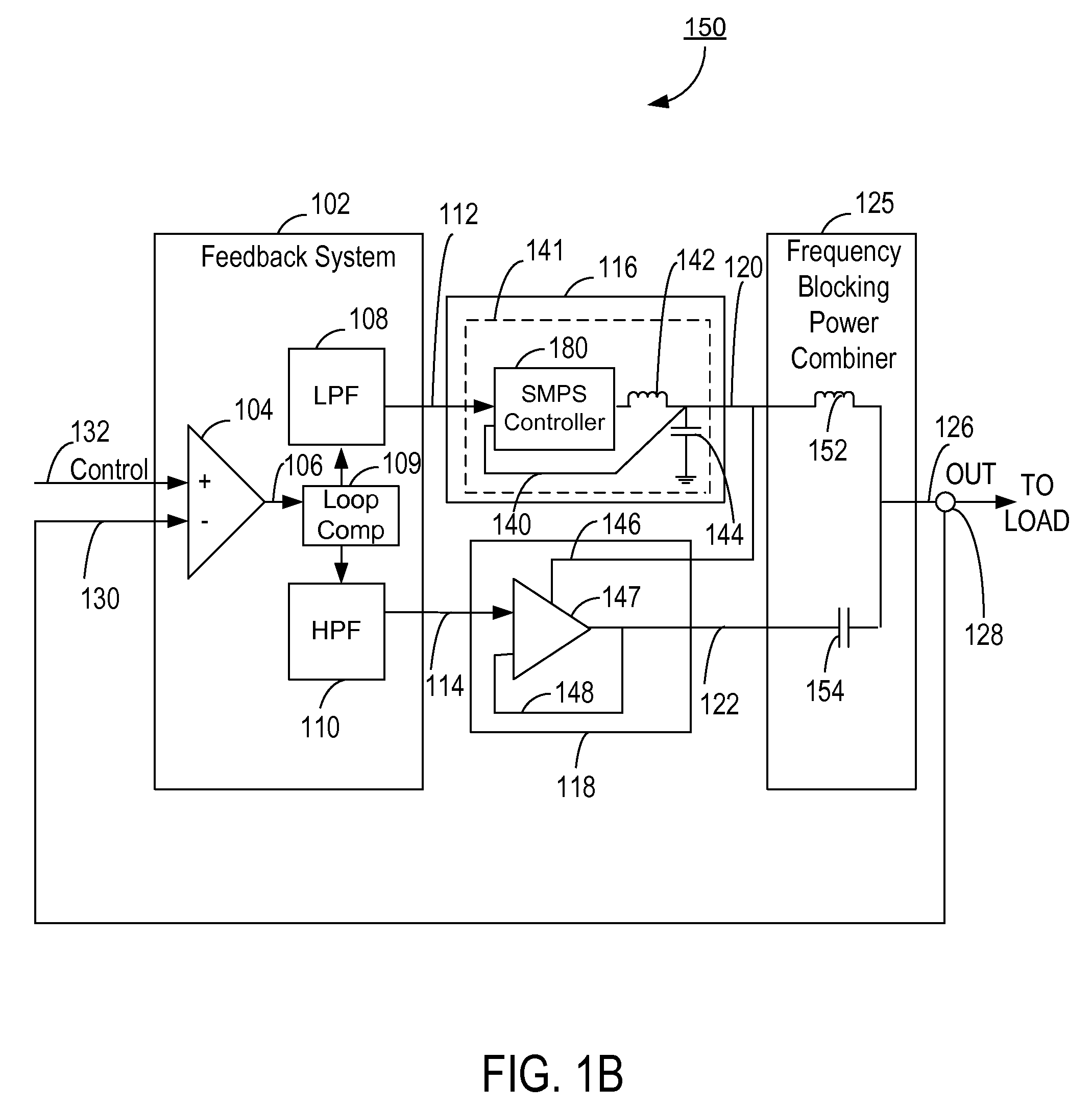
[0029]FIG. 1B illustrates a power supply system 150 with a frequency blocking power combiner 125 according to the present invention. The power supply system 150 includes a low-speed power supply 116, comprising SMPS 141 in this example. The SMPS 141 includes an SMPS controller 180, an inductor 142, an output capacitor 144, and a local feedback loop 140 for regulating the SMPS 141. Note that FIG. 1B merely illustrates a simplified conceptual view of the SMPS 141, and not all components of the SMPS 141 are shown in FIG. 1B. The SMPS 141 can be, in this example, a step-down (buck) design, with inductor 142 being the switching inductor of the SMPS 141 and the capacitor 144 being the output capacitor of the SMPS 141, although other switching regulator topologies could be used. The SMPS controller 180 operates by attempting to equalize the voltage at the low-speed power supply control 112 with the voltage at its output 120. Other details of the SMPS controller 180 are not necessary to be ...

second embodiment

[0040]FIG. 1C illustrates a power supply system 170 with a frequency blocking power combiner 127 according to the present invention. The power supply system 170 of FIG. 1C is substantially the same as the power supply system 150 of FIG. 1B, except that the frequency blocking combiner 127 in this embodiment is comprised of the transformer 160, the capacitor 154, and the resistor 156.

[0041]The frequency blocking power combiner 127 in this embodiment includes a transformer 160 to sum the output current 122 from the push-pull regulator 147 to the output current 120 from the SMPS 141. As shown in FIG. 1C, the transformer 160 has its node 1 coupled to the output 120 of the SMPS 141, node 2 coupled to the output 126 of the power supply system 170, node 3 coupled to ground, and node 4 coupled to the output 122 of the push-pull regulator 147. The primary side of the transformer 160 acts as a low pass filter for the output 120 of the SMPS 141 and thus provides the ripple filtering function de...


PUM


Abstract

A power supply system comprises a low-speed power supply and a high-speed power supply configured to operate in first and second frequency ranges, respectively, and generate first and second outputs, respectively. The lower end of the second frequency range is at least higher than a lower end of the first frequency range. A frequency blocking power combiner circuit combines the power from the first output with the power from the second output to generate a combined, third output for driving a load, while providing frequency-selective isolation between the first and second outputs. A feedback circuit is coupled to receive the combined, third output through a global feedback loop. The feedback circuit generates first and second power supply control signals for controlling the low-speed power supply and the high-speed power supply, respectively, based on a difference between the third output and the predetermined control signal.

Description

CROSS-REFERENCE TO RELATED APPLICATION[0001]This application claims priority under 35 U.S.C. §119(e) from co-pending U.S. Provisional Patent Application No. 60 / 863,548, entitled “Power Combiner,” filed on Oct. 30, 2006, the subject matter of which is incorporated by reference herein in its entirety.BACKGROUND OF THE INVENTION[0002]1. Field of the Invention[0003]The present invention relates to a power supply and, more specifically, to a power supply system that combines power output from two or more powers supplies.[0004]2. Description of the Related Art[0005]Many electronic devices tend to require much more sophisticated power supplies for supplying power. For example, many electronics may require high frequency, high overall efficiency, fewer components, and / or low ripple in the power supplied by the power supplies.[0006]More specifically, there is often a need for a power supply circuit that is capable of delivering power with high frequency components (fast changing voltage and ...

Claims


Application Information

Patent Timeline
Patent Type & Authority Applications(United States)
IPC IPC(8): G06F1/26
CPCG06F1/26H03F1/0238H02M3/1584H02M1/15
Inventor VINAYAK, VIKASDROGI, SERGE FRANCOISTOMASZ, MARTIN
Owner QUANTANCE
Why Eureka
Try Eureka