Method for drying coating film, apparatus therefor, and optical film using the same

a coating film and optical film technology, applied in drying machines with progressive movements, lighting and heating apparatus, furniture, etc., can solve the problems of not reaching a sufficient level in the application field to which a higher quality is required, and achieve the effect of preventing uneven drying and high precision

Inactive Publication Date: 2008-05-08
FUJIFILM CORP
View PDF1 Cites 26 Cited by
  • Summary
  • Abstract
  • Description
  • Claims
  • Application Information

AI Technical Summary

Benefits of technology

[0009] The present invention is designed with respect to the above described circumstances, and is directed at providing a method for drying a coating film, which can prevent the unevenness of drying with high accuracy.
[0012] The method according to the first aspect supplies air so that the drying air containing the turbulent airflow of the boundary layer formed in the vicinity of the inner wall surface of the air-supplying nozzle does not directly hits the surface of the coating film, and accordingly can prevent the unevenness of drying.
[0015] The method according to the third aspect can prevent the boundary layer component produced on the inner wall surface of the air-supplying nozzle from directly hitting the surface of the coating film, with an easy process.
[0018] The method according to the fifth aspect removes a turbulent airflow in the boundary layer, which has been formed in the vicinity of the inner wall surface of the air-supplying nozzle, can supply stable drying air to a drying zone, and accordingly can prevent the unevenness of drying.
[0020] The method according to the sixth aspect can more reliably remove the turbulent airflow of the boundary layer, which has been formed when air passes through the inner wall surface of the air-supplying nozzle, and accordingly can surely inhibit the unevenness of drying.
[0026] Method and apparatus according to the present invention can prevent an unevenness of drying with high precision.

Problems solved by technology

H02-58554, Japanese Patent Application Laid-Open No. 2001-170547, Japanese Patent Application Laid-Open No. 2005-81257 and Japanese Patent Application Laid-Open No. 2005-114188 could inhibit the unevenness of drying due to a turbulent airflow to some extent, but have not reached a sufficient level for application fields to which a higher quality is required.

Method used


Image

  • Method for drying coating film, apparatus therefor, and optical film using the same
  • Method for drying coating film, apparatus therefor, and optical film using the same
  • Method for drying coating film, apparatus therefor, and optical film using the same

Examples


examples

[0203] Examples of drying a coating film containing an organic solvent according to the present invention will be described below with reference to an example of an optical compensation sheet.

[0204] At first, an outline of a process for producing the optical compensation sheet will now be described. FIG. 12 is an explanatory view for describing the process of producing the optical compensation sheet to which a method for drying a coating liquid according to the present invention is applied. Incidentally, the figure describes the process with reference to the example of employing a drying apparatus 16 described in the first embodiment.

[0205] As shown in FIG. 12, a pay-off machine 104 pays off a web 12 which is a transparent support having a polymer layer for forming an orientational film formed thereon, and sends the web 12 to a rubbing treatment device 108 while a plurality of guide rollers 106 support the web 12. A rubbing roller 110 is installed for rubbing-treating the polymer ...

example a

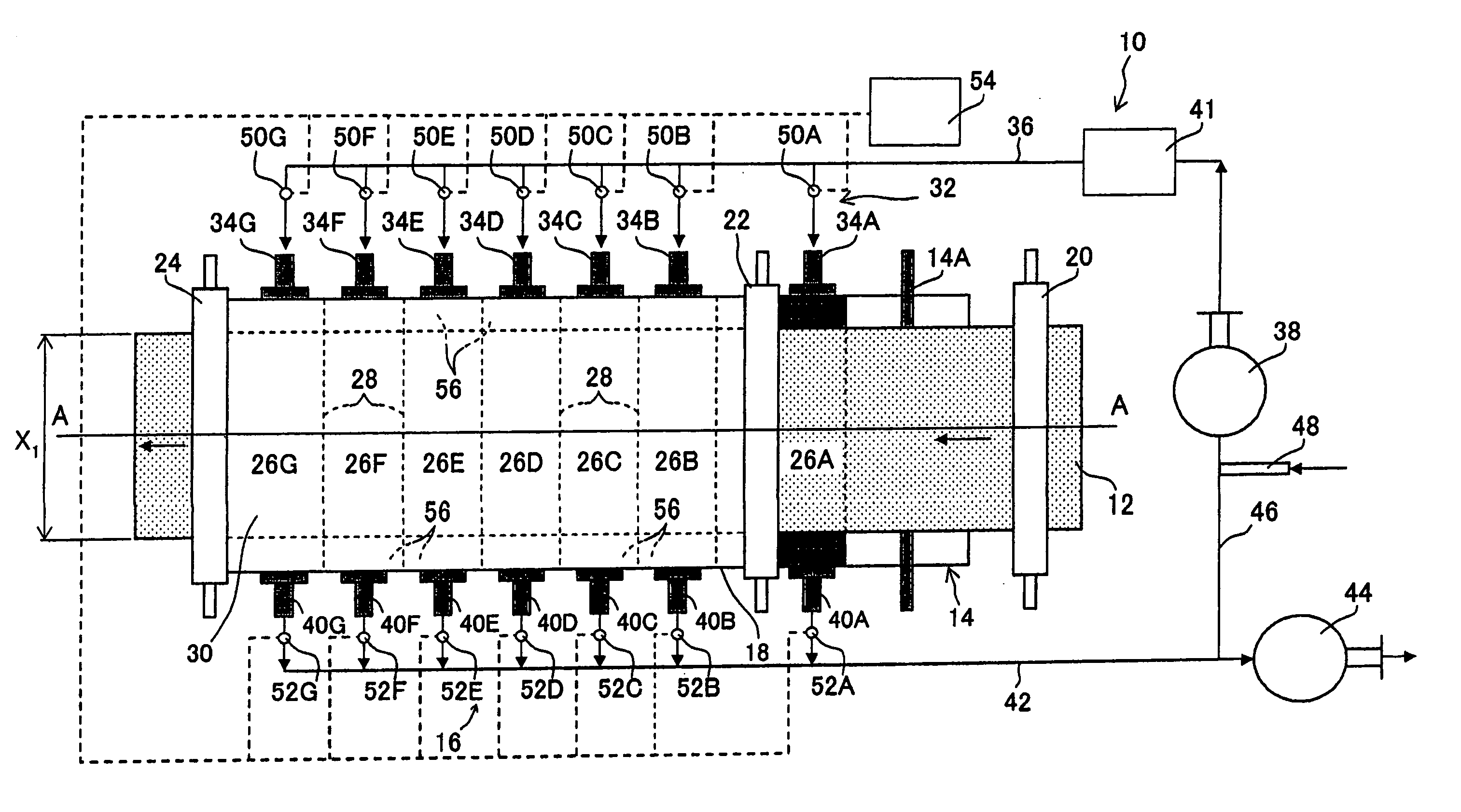
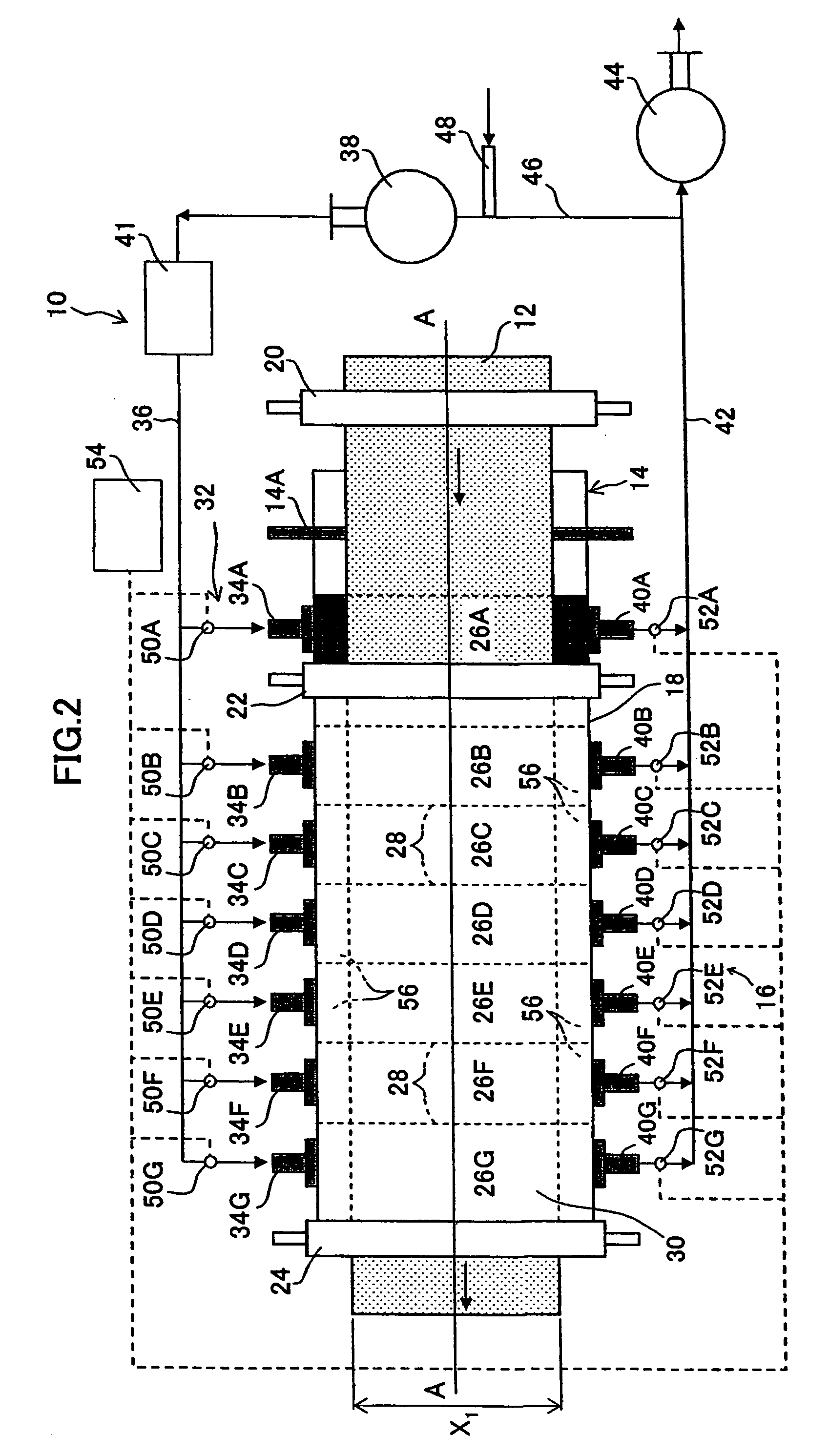
[0214] In the present example, a drying apparatus 16 in FIG. 5 was employed, and the position of a supply opening 33 with respect to a web 12 was varied. Then, it was examined whether the dried web forms the unevenness of drying or not. Specifically, in the present example, a clearance (Y) was varied which is a distance between the web and an upper side inner wall surface among inner wall surfaces of air-supplying nozzles 34A to 34G, and in which a Y1 direction (upward) perpendicular to the surface of a coating film is determined to be a positive direction, and a Y2 direction (downward) is determined to be a negative direction.

[0215] It is noted that a diameter d of the supply opening 33 in Y1-Y2 direction is 30 mm and a height D of the drying zone 26 in Y1-Y2 direction is 75 mm.

TABLE 1Clearance (Y)(mm) from innerAir velocity (m / sec)wall surfacein zones 1 to 4Surface stateExample 1−51.0GoodExample 2−101.0GoodExample 3−151.0ExcellentExample 4−151.5ExcellentExample 5−153.0FairExamp...

example b

[0219] Next, optical compensation sheets were prepared by using a drying apparatus 70 shown in FIG. 7, and the unevenness of drying produced on the sheets was visually inspected, as in the case of Example (A).

[0220] The used drying apparatus 72 had four air-supplying nozzles 90 arranged in an upstream in a drying zone 80, and an exhaust portion 84 arranged in the downstream. A clearance between the surface of the coating film on a web 12 and a supply opening 90A was set at 20 mm. The size of the supply opening 90A was set at 1,000 mm×50 mm. In addition, a pair of suction chambers 62 having a section size of 1,000×20 mm (depth (d): 25 mm) was provided in the perimeter of the supply opening 90A (see FIG. 8).

[0221] Samples were prepared by varying a ratio (suction rate) of a supplied amount to a sucked amount of drying air per one air-supplying nozzle 90 as is shown in Table 2, and it was examined whether the samples show the unevenness of drying or not.

TABLE 2SuppliedSuckedLineara...


PUM

PropertyMeasurementUnit
widthaaaaaaaaaa
wet thicknessaaaaaaaaaa

Abstract

An aspect of the present invention provides a method for drying a coating film that has been formed by applying a coating liquid to a traveling long support, by forming a tunnel-shaped drying zone so as to surround the support, and supplying drying air into the drying zone from a rectangular air-supplying nozzle which faces to the drying zone, wherein the air-supplying nozzle is designed so that among layer components of the drying air which is supplied from the air-supplying nozzle, a boundary layer component which has flowed in the vicinity of the inner wall surface of the air-supplying nozzle and is supplied from the nozzle cannot hit the surface of the coating film, while there are the boundary layer component and a central layer component which has flowed in a central part of the air-supplying nozzle and is supplied from the nozzle, in the layer components.

Description

BACKGROUND OF THE INVENTION [0001] 1. Field of the Invention [0002] The present invention relates to a method for drying a coating film, an apparatus therefor, and an optical film using the same, and particularly relates to a method for drying a coating film which is formed by applying a coating liquid onto a traveling long support (hereafter referred to as web) so that the coating film does not form an unevenness of drying, an apparatus therefor, and an optical film using the same. [0003] 2. Description of the Related Art [0004] When drying a coating film formed by applying a coating liquid containing an organic solvent onto a continuously traveling support, drying air is usually supplied and exhausted so as to promote drying. However, the method has a problem of forming an unevenness of drying (for instance, streak defect due to the unevenness of film thickness) on the surface of the coating film after having been dried, because a supplied and exhausted turbulent drying air direct...

Claims


Application Information

Patent Timeline
Patent Type & Authority Applications(United States)
IPC IPC(8): G03C1/74F26B21/00
CPCF26B13/10F26B21/004Y10T428/24942G03C1/74F26B21/12
Inventor YAHIRO, TAKASHI
Owner FUJIFILM CORP
Why Eureka
Try Eureka