Lightweight Concrete Wall Panel With Metallic Studs

a technology of metallic studs and concrete walls, which is applied in the direction of building components, construction, construction materials, etc., can solve the problems of increasing costs, many of the previously used building panels are prone to cracks and other damage, etc., to achieve excellent protection from the outside elements, reduce construction costs, and reduce construction costs

Inactive Publication Date: 2008-05-08
OLDCASTLE PRECAST
View PDF99 Cites 25 Cited by
  • Summary
  • Abstract
  • Description
  • Claims
  • Application Information

AI Technical Summary

Benefits of technology

[0010]It is one aspect of the present invention to provide a lightweight wall panel. More specifically, embodiments of the present invention are comprised of a plurality of lightweight foam insulative blocks separated by metal studs. The metal studs provide sufficient compressive strength to the wall panel. In addition, a layer of lightweight concrete is employed on one side of the insulative foam blocks to provide a surface that is resistant to heat, cold, wind, water and other natural conditions. The wall panel as provided herein is contemplated to become an exterior of a building. However, one skilled in the art will appreciate that the wall panel as disclosed herein is ideal for interior walls of a building. The insulative foam blocks provide thermal isolation between the metal components of the wall and the concrete components of the wall. In addition, the insulation provides an

Problems solved by technology

Previous attempts to provide these types of building panels have failed due to the expensive transportation costs and less than ideal insulative and thermal conductivity properties associated with prefabricated concrete wire- reinforced products.
Further, due to the brittle nature of concrete, many of the previously used building panels are prone to cracks and other damage during transportation.
The relatively large weight per square foot of building panels of the prior art has resulted in increased expenses arising not only from the amount of materials needed for fabrication, but also the cost of transporting and erecting the modules.
Building panel weight also places effective limits on the height of structures, such as stacked modules e.g., due to load limitations of the building foundations, footings and/or lowermost modules.
Furthermore, there is substantial fabrication labor expense that can arise from design, material, and labor costs associated with providing and integrating reinforcement materials.
In some previous approaches, wall panels were cast so as to include any necessary openings that require careful planning and design, thus increasing costs.
Such post-casting procedures, for example cutti

Method used


Image

  • Lightweight Concrete Wall Panel With Metallic Studs
  • Lightweight Concrete Wall Panel With Metallic Studs
  • Lightweight Concrete Wall Panel With Metallic Studs

Examples


Embodiment Construction

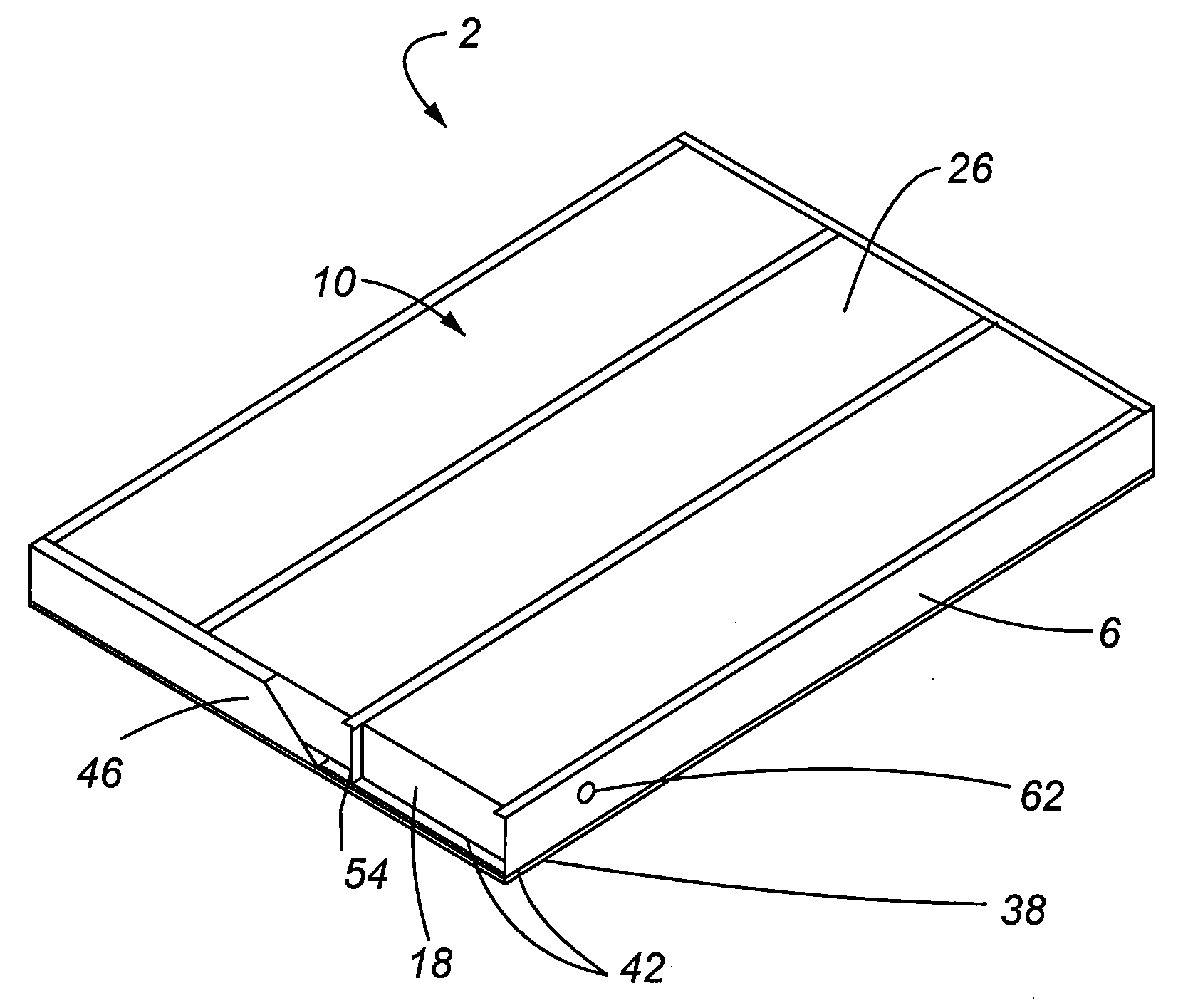
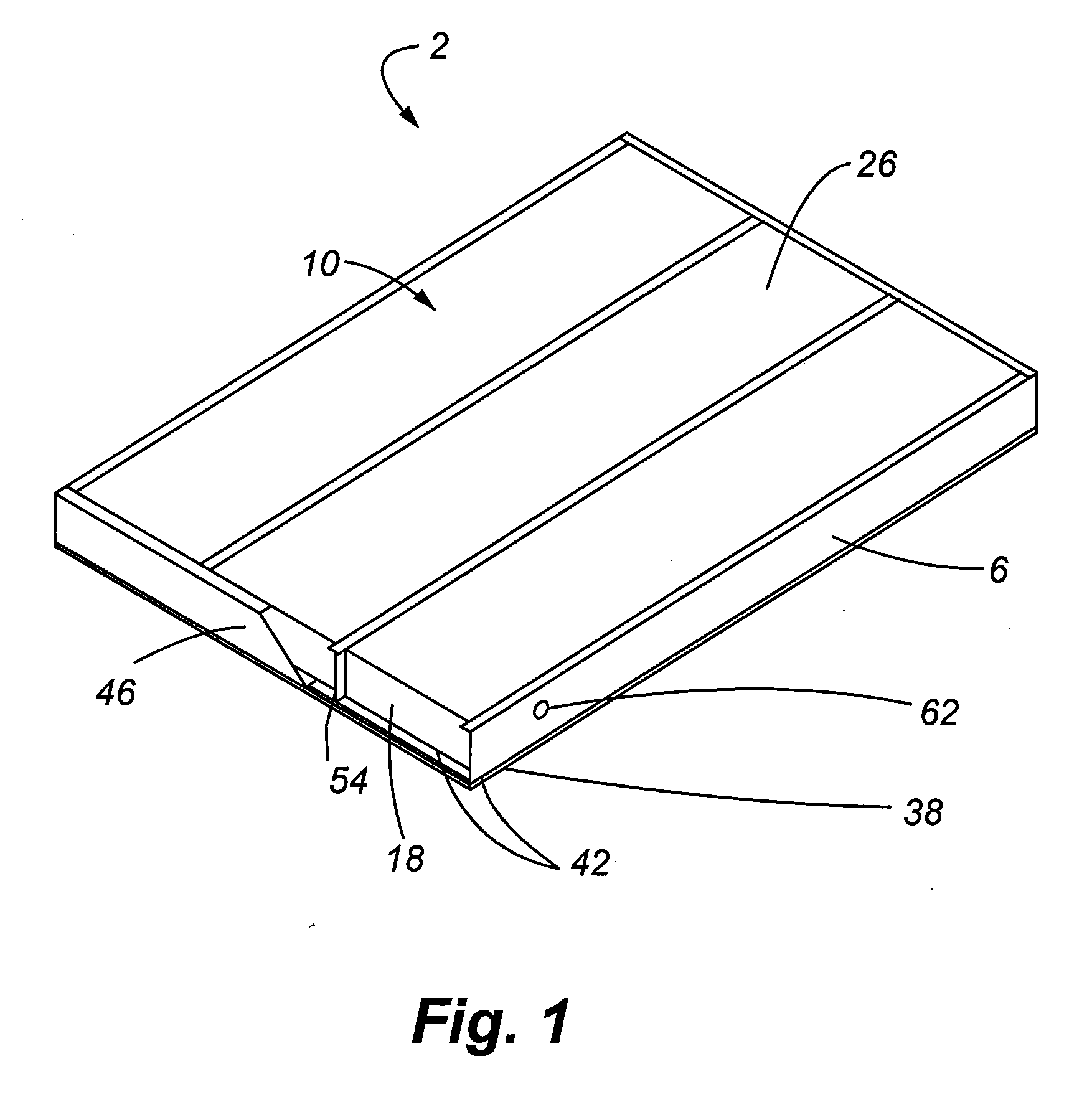
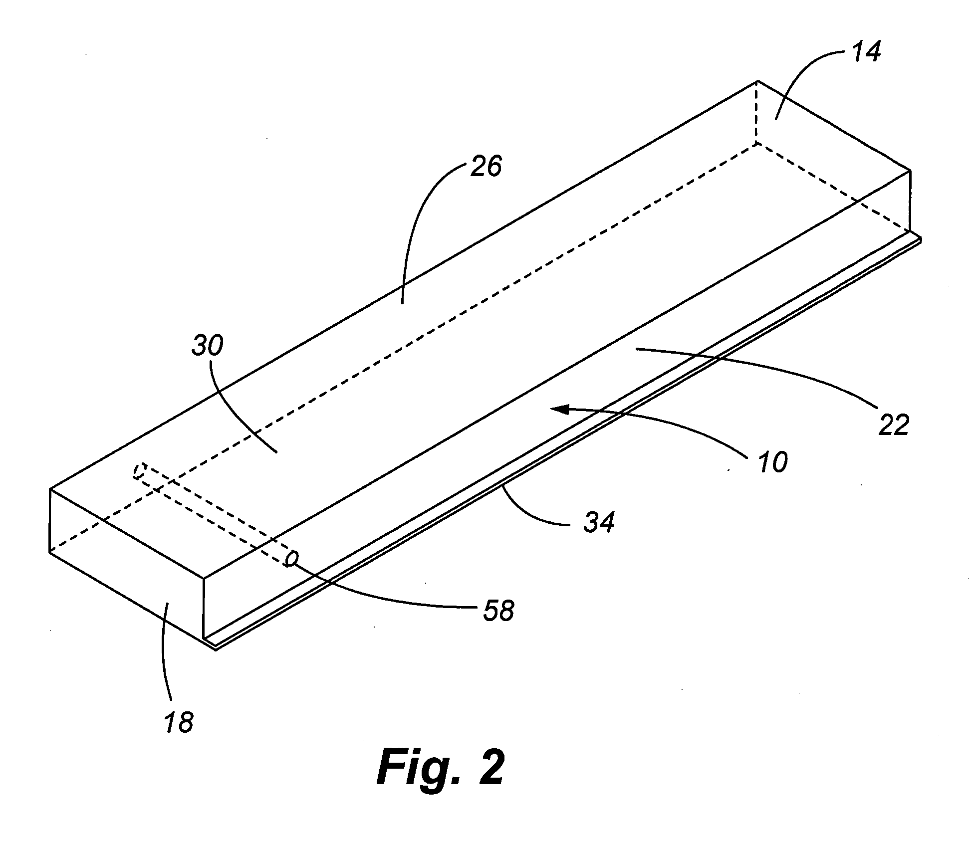
[0046]Referring now to FIGS. 1-5, a lightweight wall panel 2 is provided that includes a plurality of metal studs 6 that receive foam insulation blocks 10 positioned therebetween. The foam blocks 10 used in the present invention are generally rectangular with an upper surface 14, a lower surface 18 and two lateral side surfaces 22. In addition, an interior 26 and exterior surface 30 is provided. Further, at least one lateral side surface has a lip 34 depending therefrom that generally extends the exterior surface 30. The lip 34 is adapted to receive the metallic stud 6 and separates the metallic stud 6 from a layer of lightweight concrete material 38 that is affixed to the exterior surface 30 of the foam block. Wall panels 2 as contemplated herein also may include insulative strips 42 adjacent to a lower surface 18 and an upper surface 14 of the foam blocks 10 that provide a location for the interconnection of a channel 46 that also interconnects to upper 50 and lower 54 edges of th...


PUM


Abstract

A wall panel is provided that is comprised of a plurality of spaced foam insulative blocks. Between each block is a metal stud that spans the height of the wall panel and provides sufficient strength to counteract any compressive loads the wall panel may encounter. The presence of the insulation panels provides large surface areas for the receipt of a thin layer of cementious or gypsum based material that is adapted to receive nails and be easily cut. In addition, the decreased weight of the exterior wall allows for the omission of reinforcing internal structure within the exterior wall which is found in the prior art, thereby providing a lightweight and easy to fabricate wall.

Description

[0001]This application claims benefit of U.S. Provisional Application Ser. No. 60 / 806,598, filed Jul. 5, 2006, the entire disclosure of which is hereby incorporated by reference.[0002]This application is also related to pending U.S. patent application Ser. No. 11 / 122,792, filed May 4, 2005, which is a continuation-in-part of pending U.S. patent application Ser. No. 11 / 096,705, filed Apr. 1, 2005, which is a continuation-in-part of pending U.S. patent application Ser. No. 10 / 772,148, filed Feb. 3, 2004, now U.S. Pat. No. 7,100,336, which is a continuation-in-part of pending U.S. patent application Ser. No. 10 / 423,286, filed Apr. 24, 2003, now U.S. Pat. No. 6,898,908, which is a continuation-in-part of U.S. patent application Ser. No. 10 / 150,465, now U.S. Pat. No. 6,729,090, filed May 17, 2002, which is a continuation-in-part of U.S. patent application Ser. No. 10 / 093,292, now U.S. Pat. No. 6,701,683, filed Mar. 6, 2002. In addition, this application is related to U.S. patent applicat...

Claims


Application Information

Patent Timeline
IPC IPC(8): E04C2/06
CPCE04C2/384E04C2/288
Inventor MESSENGER, HAROLD G.BUI, THUANHARMON, THOMAS G.
Owner OLDCASTLE PRECAST
Why Eureka
Try Eureka