Dynamic floating input d flip-flop

a flip-flop and input technology, applied in the field of d flip-flops, can solve the problems that the 1/16 frequency dividing circuit formed by the conventional tgffs cannot achieve high speed operation, reduce the operating frequency, and operating voltage, and achieve the effect of reducing the power consumption of short circuit current and dc curren

Active Publication Date: 2008-05-08
IND TECH RES INST
View PDF10 Cites 15 Cited by
  • Summary
  • Abstract
  • Description
  • Claims
  • Application Information

AI Technical Summary

Benefits of technology

[0014]The present invention provides a D flip-flop circuit, which is capable of reducing the power consumption of the short circuit current and the dc current and has preferred power-delay product (PDP).

Problems solved by technology

However, in practice, it is necessary to correspondingly reduce the operating frequency to reduce the operating voltage.
In view of the above, the 1 / 16 frequency dividing circuit formed by the conventional TGFFs cannot achieve the high speed operation.
However, because the number the of metal oxide semiconductor (MOS) transistors connected in series in the conventional art is larger (as shown in FIG. 2, the number of the MOS transistors connected in series is four at most), the whole speed is affected when operating in low voltage.
However, because the circuit connecting manner may generate large short circuit current and dc current, a lot of power consumption may be resulted.
Particularly in the low speed, the short circuit current and the dc current take more than half of the total power consumption.
Although under the low voltage, the operating frequency of the conventional D flip-flop circuits as shown in FIGS. 4 and 5 may be more than 500 MHz, because of the connecting manner of the flip-flop circuit, it is much possible to generate the short circuit current and the dc current, thereby consuming a lot of power.

Method used


Image

  • Dynamic floating input d flip-flop
  • Dynamic floating input d flip-flop
  • Dynamic floating input d flip-flop

Examples


Embodiment Construction

[0036]In the following- embodiments, when an element is connected or coupled to another element, it may be directly connected to or coupled to another element, or an element may be sandwiched there between. Oppositely, when an element is directly connected or directly coupled to another element, the element sandwiched there between does not exist.

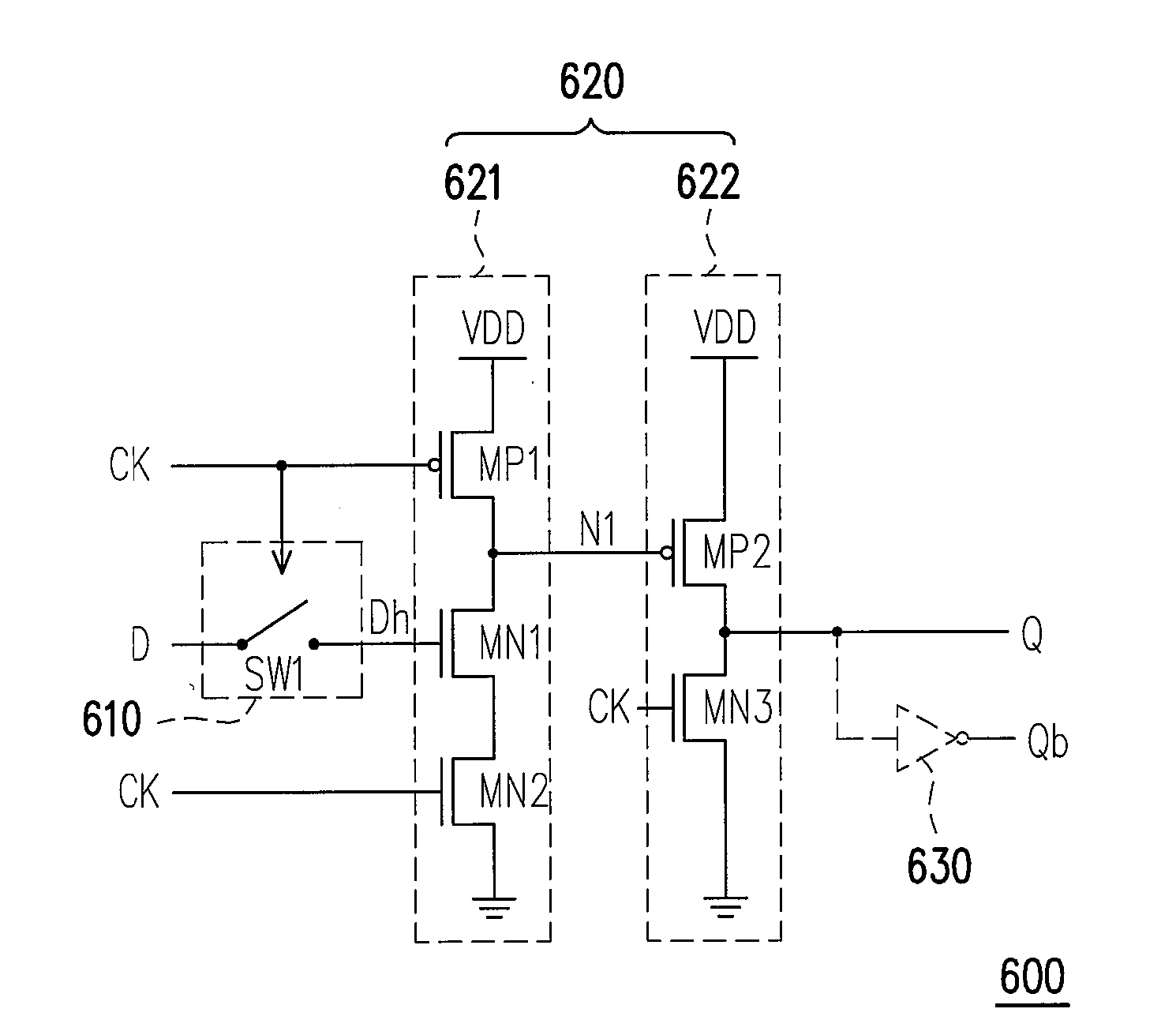
[0037]FIG. 6 is a circuit diagram of a DFIDFF according to an embodiment of the present invention. Referring to FIG. 6, the DFIDFF 600 includes a floating input stage 610, and a latch stage 620. At a pre-charge period, the floating input stage 610 transmits an input data D to an output end (i.e. to a node Dh) in accordance with the timing of a clock signal CK. The latch stage 620 includes a first string of transistor 621 and a second string of transistor 622. An input node Dh of the string of transistors621 is coupled to the output end of the floating input stage 610. In accordance with the timing of the clock signal CK, at the pre-charge p...


PUM


Abstract

A dynamic floating input D flip-flop (DFIDFF) is provided. The DFIDFF includes a floating input stage, a first string of transistors, and a second string of transistors. At a pre-charge period, the floating input stage transmits the input data to the first string of transistors; the first string of transistors stores the logic status of the input data, and pre-charges its output node to a first level. At an evaluation period, the first string of transistors decides its output node level in accordance with data logic status stored in the first string of transistors; and the second string of transistors decides output level of the D flip-flop in accordance with logic status of the output node of the first string of transistors.

Description

CROSS-REFERENCE TO RELATED APPLICATION[0001]This application claims the priority benefit of Taiwan application serial no. 95139968, filed Oct. 30, 2006. All disclosure of the Taiwan application is incorporated herein by reference.BACKGROUND OF THE INVENTION[0002]1. Field of Invention[0003]The present invention relates to a D flip-flop. More particularly, the present invention relates to a dynamic floating input D flip-flop (DFIDFF).[0004]2. Description of Related Art[0005]Recently, with the development of the process, handheld electronic products have become the necessary tools in life. For the handheld electronic products, it is an important topic on the product design that the power consumption is saved to increase the lifetime of the cell and to prolong the service time of the handheld electronic product. Viewing from the power consumption formula P=αcV2f, it is the most effective method to reduce the operating voltage. P is the power consumption, α is the activity coefficient, c...

Claims


Application Information

Patent Timeline
Patent Type & Authority Applications(United States)
IPC IPC(8): H03K3/00
CPCH03K19/0963
Inventor JAU, TING-SHENGYANG, WEI-BINLO, YU-LUNG
Owner IND TECH RES INST
Why Eureka
Try Eureka