Thin film transistor array substrate and fbricating method thereof

a thin film transistor and array substrate technology, applied in the direction of basic electric elements, semiconductor devices, electrical equipment, etc., can solve the problems of increased manufacturing cost, power consumption, signal distortion, etc., to reduce manufacturing cost, simplify the manufacturing process, and reduce the effect of masking process

Active Publication Date: 2008-05-15
AU OPTRONICS CORP
View PDF7 Cites 13 Cited by
  • Summary
  • Abstract
  • Description
  • Claims
  • Application Information

AI Technical Summary

Benefits of technology

[0008]Accordingly, the present invention is directed to provide a method of fabricating a thin film transistor (TFT) array substrate, wherein transmissive common lines are fabricated with less mask processes to simplify the fabricating process and further to reduce fabricating cost.
[0009]The present invention is also directed to a TFT array substrate of low fabricating cost, and the TFT array substrate has improved pixel aperture ratio.
[0010]The present invention is further directed to a TFT array substrate having high pixel aperture ratio, wherein the common lines of the TFT array substrate have both transmissive and very good conductive characteristics such that signal distortion is reduced.
[0031]According to the fabricating method of a TFT array substrate in an embodiment of the present invention, at least a part of each common line is fabricated with transparent conductive material to improve pixel aperture ratio, and the transparent conductive patterns for forming the common lines may be defined with the same mask as that for defining the semiconductor layer to reduce the required mask processes and further to reduce the fabricating cost. Moreover, in the present invention, the common lines on the TFT array substrate may also be formed by connecting the metal patterns and the transparent conductive patterns so that the common lines may have lower resistance, accordingly the power consumption of the TFT array substrate may be reduced and signal distortion may be avoided.

Problems solved by technology

However, an additional mask process for defining the common lines is required when fabricating the common lines with conductive material, thus, the manufacturing cost is increased, and since the resistance of the conductive material is higher than that of conventionally used metal material, power consumption and accordingly signal distortion may be caused.

Method used


Image

  • Thin film transistor array substrate and fbricating method thereof
  • Thin film transistor array substrate and fbricating method thereof
  • Thin film transistor array substrate and fbricating method thereof

Examples


first embodiment

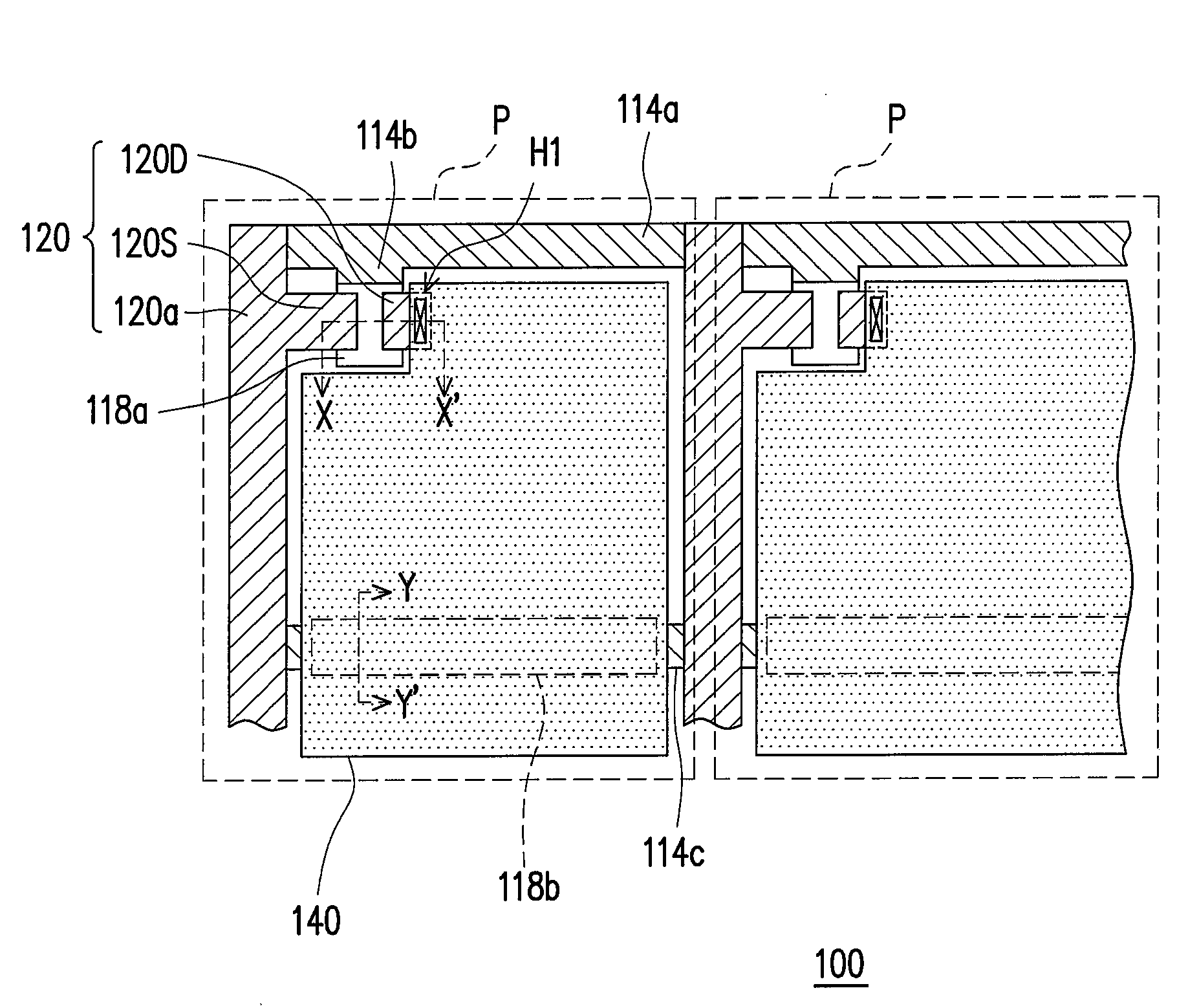
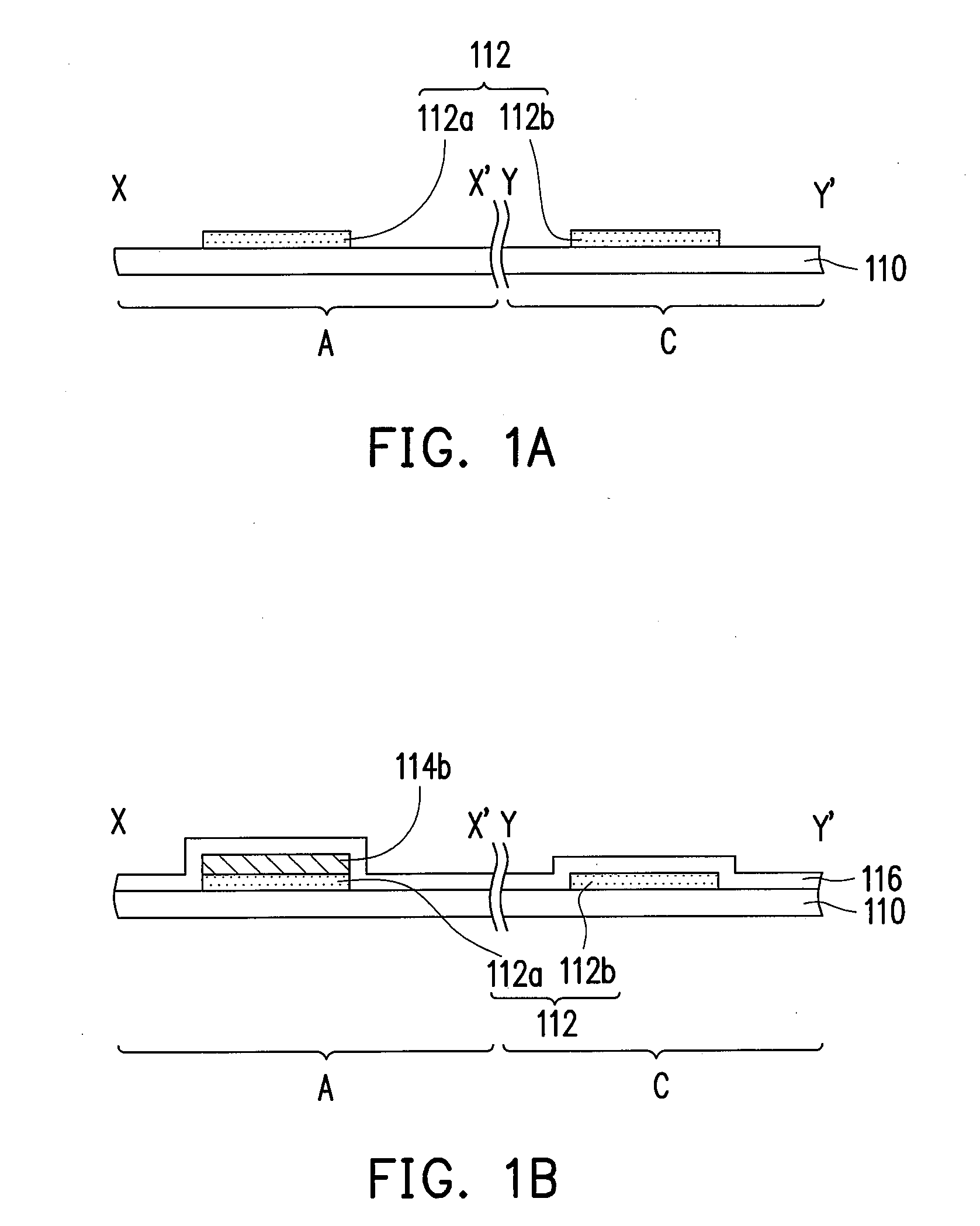
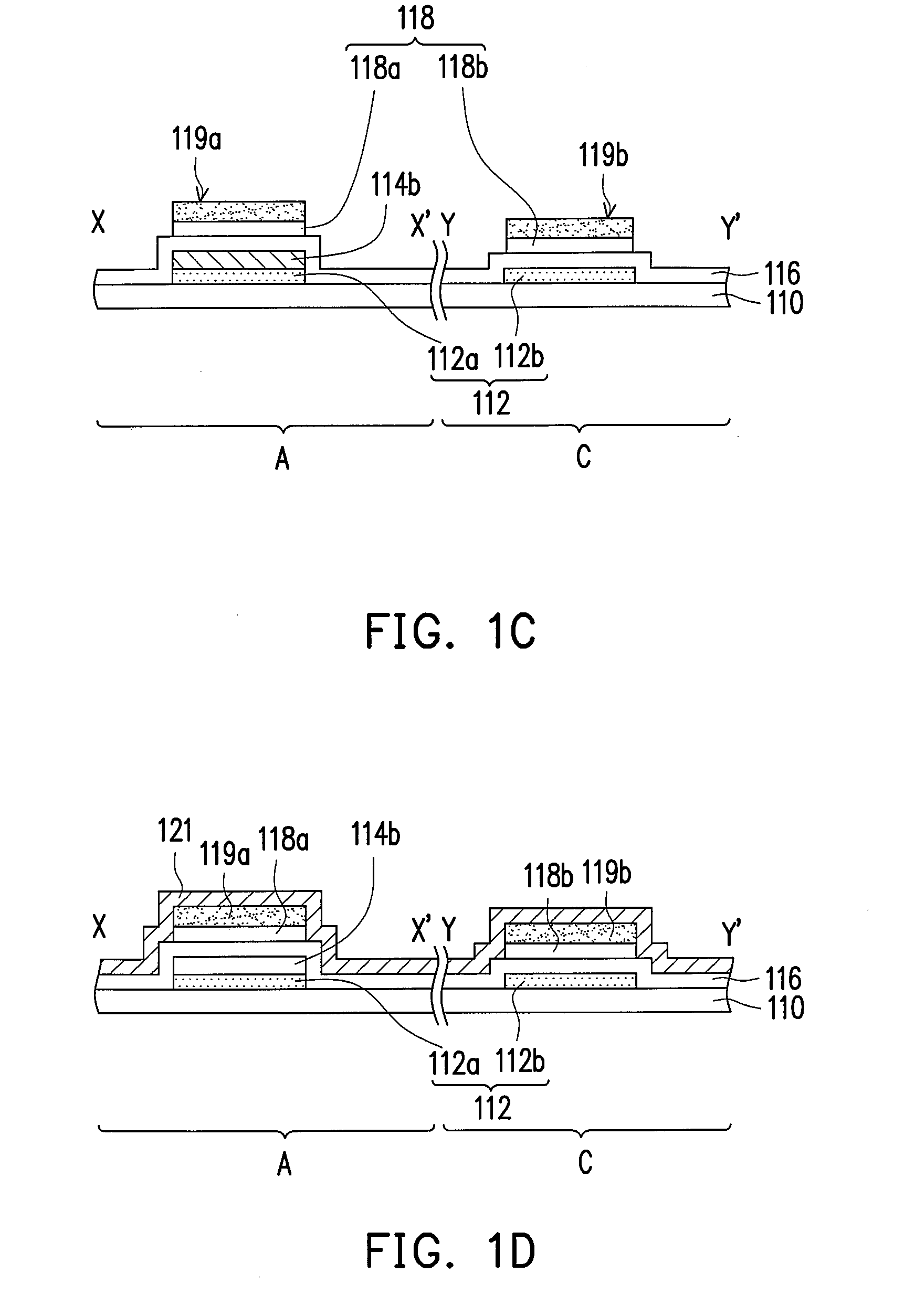
[0039]FIGS. 1A˜1H are cross-sectional views illustrating the fabricating flow of a thin film transistor (TFT) array substrate according to a first embodiment of the present invention, and FIGS. 2A˜2E are top views illustrating the fabricating flow of the TFT array substrate according to the first embodiment of the present invention. Referring to FIG. 1A and FIG. 2A, first, a substrate 110 is provided, and the substrate 110 has a plurality of pixel preset regions P arranged as an array (only two pixel preset regions P are illustrated demonstratively in FIG. 2A), and each pixel preset region P has an active device region A and a capacitor region C. A patterned transparent conductive layer 112 is then formed on the substrate 110 to form a first transparent conductive pattern 112a in each active device region A and a second transparent conductive pattern 112b in each capacitor region C.

[0040]To be specific, the transparent conductive layer 112 may be formed by depositing a transparent c...

second embodiment

[0053]FIGS. 3A˜3H are cross-sectional views illustrating the fabricating flow of a TFT array substrate according to a second embodiment of the present invention, and FIGS. 4A˜4F are top views illustrating the fabricating flow of the TFT array substrate according to the second embodiment of the present invention. Referring to FIG. 3A and FIG. 4A, a substrate 110 is first provided and the substrate 110 has a plurality of pixel preset regions P arranged as an array (only two pixel preset regions P are illustrated demonstratively in FIG. 4A). Each of the pixel preset regions P has an active device region A and a capacitor region C. A patterned transparent conductive layer 112 is then formed on the substrate 110 to form a first transparent conductive pattern 112a in each active device region A and a second transparent conductive pattern 112b in each capacitor region C. It should be noted here that the second transparent conductive patterns 112b in adjacent pixel preset regions P are conn...


PUM


Abstract

A thin film transistor array substrate and a fabricating method thereof are disclosed. First, a substrate is provided. A patterned transparent conductive layer is then formed on the substrate. Next, a patterned first metal layer is formed to form a plurality of scan lines and a plurality of gates. Thereafter, a gate insulation layer is formed over the substrate. Moreover, a patterned semiconductor layer is formed to form a channel layer above the gates. The semiconductor layer is patterned with the same mask as that for patterning the transparent conductive layer. Additionally, a patterned second metal layer is formed to form a plurality of data lines, a plurality of sources, and a plurality of drains. After that, a dielectric layer is formed over the substrate. Finally, pixel electrodes are formed on the dielectric layer.

Description

CROSS-REFERENCE TO RELATED APPLICATION[0001]This application claims the priority benefit of Taiwan application serial no. 95141894, filed Nov. 13, 2006. All disclosure of the Taiwan application is incorporated herein by reference.BACKGROUND OF THE INVENTION[0002]1. Field of the Invention[0003]The present invention relates to an active device array substrate and a fabricating method thereof. More particularly, the present invention relates to a thin film transistor (TFT) array substrate and a fabricating method thereof.[0004]2. Description of Related Art[0005]Currently, the multimedia technology has become very developed due to the advancement of semiconductor devices or display apparatuses. As to displays, liquid crystal display (LCD) having such characteristics as high image quality, high space efficiency, low power consumption, and no radiation has become the mainstream in the display market.[0006]An LCD panel includes a thin film transistor (TFT) array substrate, a color filter s...

Claims


Application Information

Patent Timeline
Patent Type & Authority Applications(United States)
IPC IPC(8): H01L29/04H01L21/00
CPCH01L27/1288H01L27/124H01L27/1214
Inventor WANG, CHING-YI
Owner AU OPTRONICS CORP
Why Eureka
Try Eureka