
Led reflective package

a reflective package and reflective technology, applied in the direction of basic electric elements, electrical equipment, semiconductor devices, etc., can solve the problems of high cost, high cost, and high cost of packaging, and achieve the effects of high reflectivity, high cost, and high thermal conductivity substra

Inactive Publication Date: 2008-05-15
IQLP
View PDF14 Cites 14 Cited by
  • Summary
  • Abstract
  • Description
  • Claims
  • Application Information

AI Technical Summary

Benefits of technology

[0007] The present invention provides an LED package which employs a high temperature plastic or polymeric material which is compatible with widely used gold-tin eutectic solder and which can replace the higher cost ceramic used in conventional LED packages. The novel LED package has a high thermal conductivity substrate, a high reflectivity for visible light and / or UV light, and good aging properties.
[0009] For an LED package which is reflective to UV light, a UV stabilizer can be included in the plastic material to improve reflectivity in the ultraviolet spectrum and to protect from UV degradation of the plastic material which can be caused by UV light emitted by some LEDs.

Problems solved by technology

In both of these cases of alumina and aluminum nitride, the manufacturing process causes the package to be cost inefficient for many applications such as high volume consumer product applications.
Also, as LED technology evolves, LED optical power is increasing, which results in the need to dissipate more heat.
The ceramic package provides good thermal conductivity but at a relatively high cost.
In addition, this plastic material has a relatively high moisture absorption of 3.9% and exhibits degradation of reflectivity during aging of the plastic material.
A major drawback of this known plastic material is a lack of compatibility with widely-used gold-tin eutectic solder, since this plastic material has a lower melting temperature than the gold-tin eutectic solder used to attach the LED to the base

Method used


Image

  • Led reflective package
  • Led reflective package
  • Led reflective package

Examples


Embodiment Construction

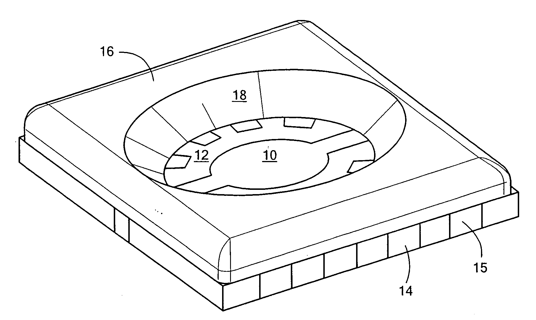
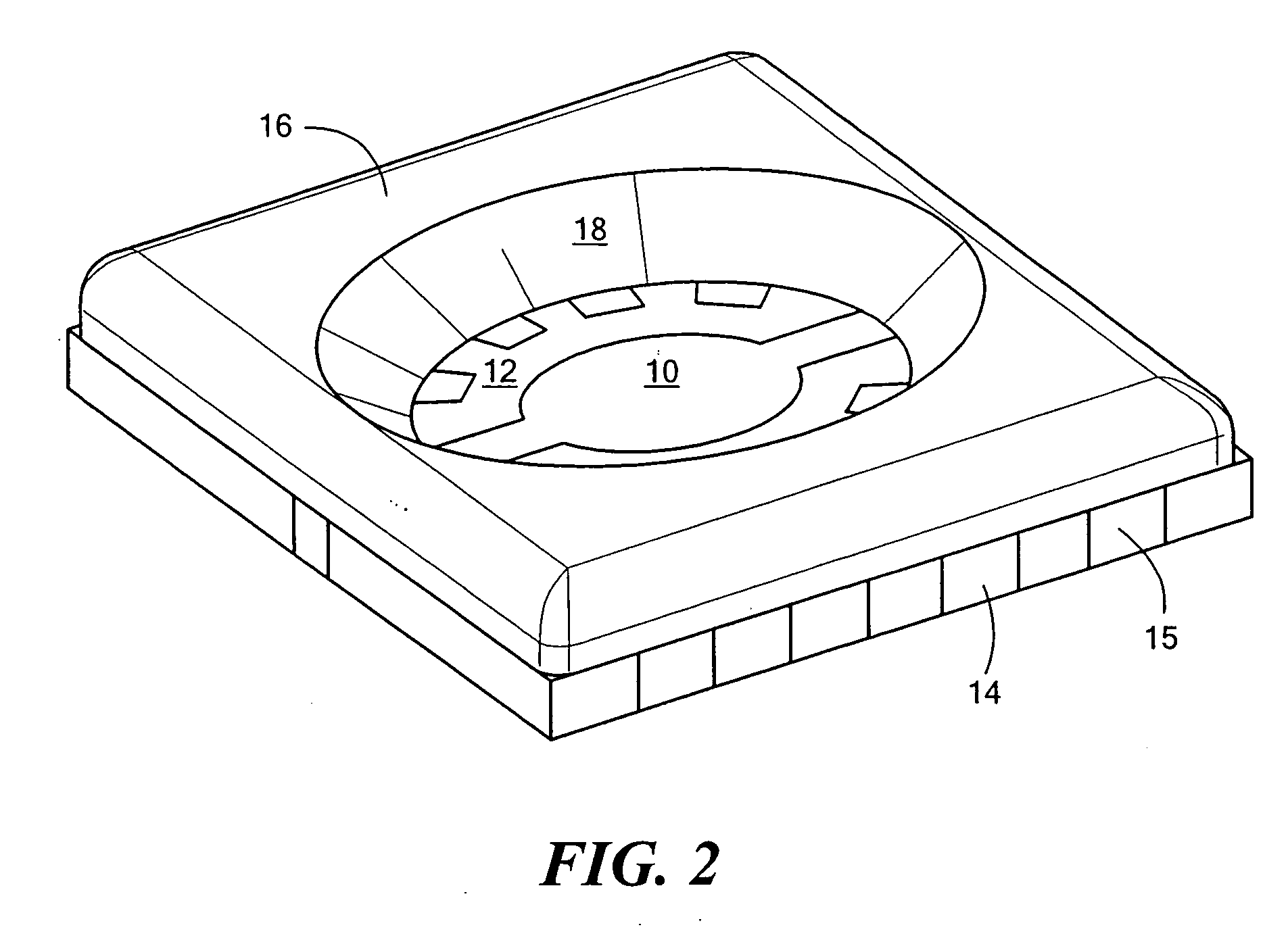
[0014] A preferred embodiment of an LED package in accordance with the invention is shown in FIG. 2. The package comprises a substrate 10 having a surface 12 on which one or more LED devices can be mounted and having an opposite surface 14 containing conductive pads 15 for surface mounting of the package to a circuit board or other mounting surface. It will be appreciated that the package can include other known electrical lead configurations to suit particular applications. A housing 16 is disposed on the surface 12 of the substrate and having a cavity surrounding the mounting area for the one or more LEDs. The housing is composed of a high temperature plastic or polymeric material, further described below, and has an angled peripheral surface 18 as shown which acts as a reflective surface for the light emitted by the one or more LEDs. After one or more LEDs are mounted on the surface 14 within the cavity area of the housing, a lens, not shown, is attached over the cavity area to c...


PUM


Abstract

An LED package which employs a high temperature plastic or polymeric material which is compatible with widely used gold-tin eutectic solder and which can replace the higher cost ceramic used in conventional LED packages. The novel LED package has a high thermal conductivity substrate, a high reflectivity for visible light and / or UV light, and good aging properties. The high temperature material is a high temperature liquid crystal polymer (LCP) having a melting temperature greater than about 340° C. and has small filler particles near the surface, the particles having a refractive index greater than about 2.0, and a size range of about 0.2 to 0.3 microns. For an LED package which is reflective to UV light, a UV stabilizer can be included in the plastic material to improve reflectivity in the ultraviolet spectrum and to protect from UV degradation of the plastic material which can be caused by UV light emitted by some LEDs.

Description

CROSS REFERENCE TO RELATED APPLICATIONS [0001] This application claims the benefit under 35 U.S.C. § 119(e) of U.S. Provisional Patent Application No. 60 / 858,018, filed on Nov. 9, 2006, the disclosure of which is incorporated by reference herein.STATEMENT REGARDING FEDERALLY SPONSORED RESEARCH OR DEVELOPMENT [0002] N / A BACKGROUND OF THE INVENTION [0003] Light emitting diode (LED) devices are made from materials such that light is transmitted either sideways or upwards from the surface of the LED. The LED simultaneously dissipates electrical energy which is converted to heat. The extraction of heat from the LED is important to the performance of the LED. Therefore, a package which provides electrical and optical connections to the LED needs to provide for both thermal and optical efficiency. For a high performance package for these applications, alumina, having a thermal conductivity of 15 W / mK, is often used. For higher thermal performance, aluminum nitride, having a thermal conduct...

Claims


Application Information

Patent Timeline
IPC IPC(8): H01L33/00H01L33/48H01L33/60
CPCH01L33/486H01L33/60H01L2924/0002H01L2924/00
Inventor ZIMMERMAN, MICHAEL A.
Owner IQLP
Learn More