Backlight module and a liquid crystal display module using the same

a technology of backlight module and liquid crystal display module, which is applied in the direction of display means, instruments, spectral modifiers, etc., can solve the problem that the entire thickness of the lcd cannot meet the slim-line trend, and achieve the effect of reducing the distance between the light-mixing unit and the bottom plate, reducing the thickness of the entire lcd module, and reducing the cos

Active Publication Date: 2008-05-15
AU OPTRONICS CORP
View PDF6 Cites 4 Cited by
  • Summary
  • Abstract
  • Description
  • Claims
  • Application Information

AI Technical Summary

Benefits of technology

[0011]In the present invention, the light-premixing unit is located above the bottom plate at a distance ranging from 4 to 6 mm. The at least one first diffuser of the light-premixing unit is a diffuser with a high diffusivity and, preferably, with a haze value greater than 70%. Such a high-diffusivity diffuser can increase the light-mixing diffusion to thereby reduce the entire thickness of the backlight module. In the light-premixing unit, a first diffuser is located on a first transparent plate. The first diffuser can diffuse the light emitted by the light sources. The material of the first diffuser can be a PC (polycarbonate), PET (polyethylene terephthalate), PS (polystyrene), PMMA (polymethyl methacrylate), or MS (methyl methacrylate-styrene copolymer). The first transparent plate is loaded on the first diffuser, and the material thereof can be any transparent material, but preferably is an acrylic material, a polycarbonate material, a cycloolefin copolymer (COC), or glass, and more preferably is the acrylic material.
[0013]Because the present invention uses the light-premixing unit to preprocess the light, the distance between the light-mixing unit and the bottom plate can be reduced to thereby reduce the entire thickness of the LCD module. The distance can be smaller than 45 mm, and preferably is smaller than 40 mm.
[0014]In the present invention, the light-premixing unit and the light-mixing unit can have the same or different material and structure. When the same material is applied to the two units, the cost is reduced and thinning the backlight module becomes more efficient.
[0015]In the present invention, the backlight module further comprises one or more optical films located on the light-mixing unit, the light-premixing unit or both. The optical films can be a prism or light-enhancing sheet. The prism or light-enhancing sheet can increase the brightness of the backlight module.
[0018]As cited, the present invention provides a backlight module to have both the illumination efficiency and the desired light-mixing effect. The light-premixing unit is added to increase diffusion of the mixed light without sacrificing the illumination efficiency of the backlight module. In addition, the thickness of the LCD module is relatively reduced to become thinner, which further provides more options for the market.

Problems solved by technology

As cited, in the aforementioned backlight module, the thickness of which is limited by the distance between the light-mixing unit and the bottom plate, so the entire thickness of the LCD cannot meet the slim-line trend.
Therefore, it becomes an important issue to shorten the distance between the light-mixing unit and the bottom plate and to provide a slim LCD to mitigate and / or obviate the aforementioned problems.

Method used


Image

  • Backlight module and a liquid crystal display module using the same
  • Backlight module and a liquid crystal display module using the same
  • Backlight module and a liquid crystal display module using the same

Examples


embodiment 1

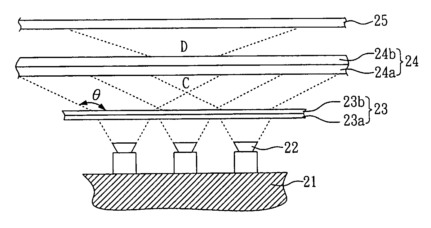
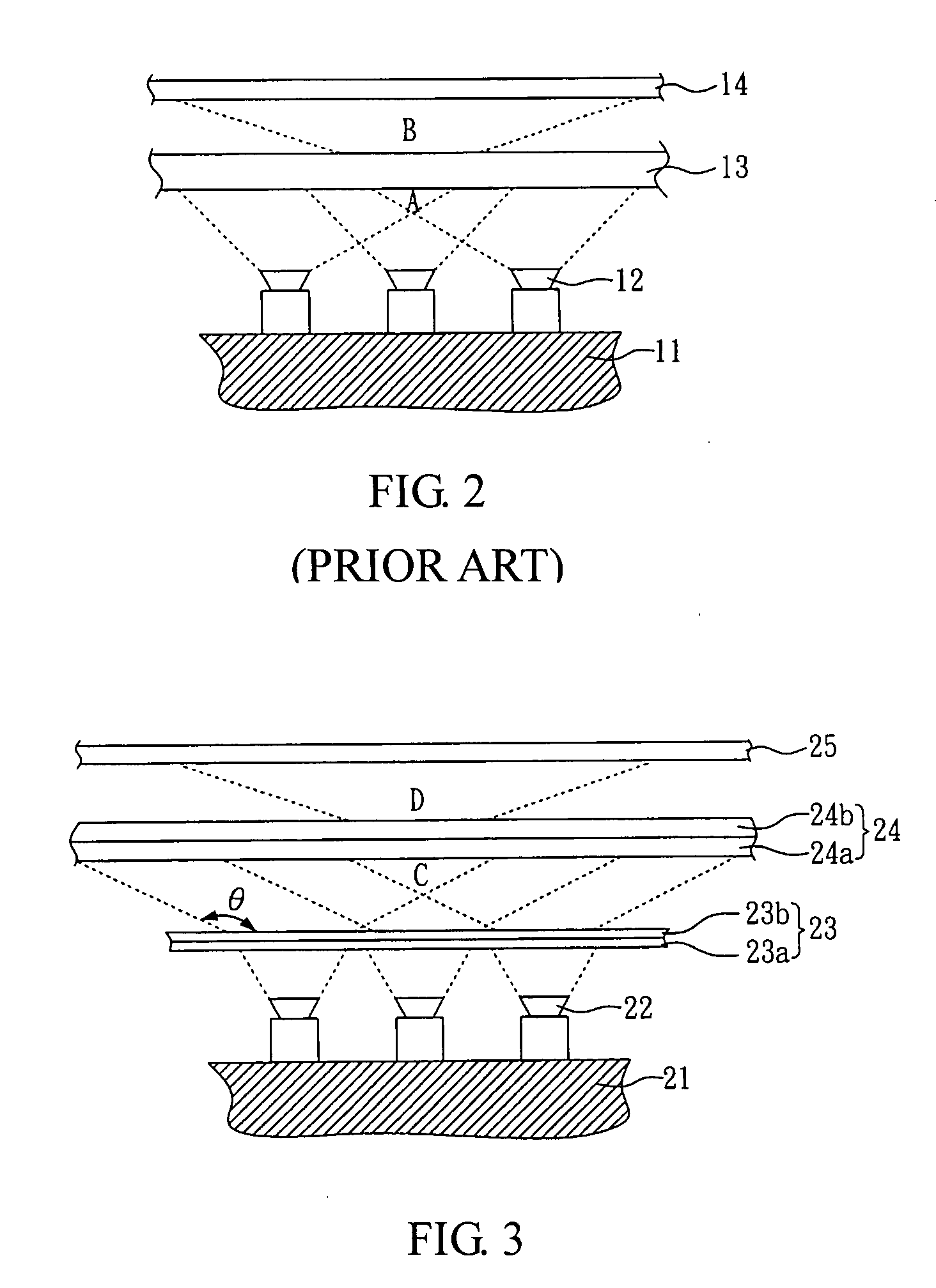
[0026]FIG. 3 is a schematic sectional view of an LCD module with a backlight module according to the present invention. As shown in FIG. 3, the backlight module includes a bottom plate 21, a plurality of light sources 22, a light-premixing unit 23 and a light-mixing unit 24. The bottom plate 21 has multiple light mounting holes (not shown). The light sources are LEDs arranged in the light mounting holes. The LEDs include red light, blue light and green light.

[0027]The light-premixing unit 23 comprises a first diffuser 23b and is located at 4-6 mm above the bottom plate 21. The light-premixing unit 23 uses the first diffuser 23b to be loaded on a first transparent plate 23a. The material of the first transparent plate 23a can be a transparent acrylic plate, where the first transparent plate 23a loads with the first diffuser 23b of high diffusivity. The material of the first diffuser 23b can be a polycarbonate (PC) or polyethylene terephthalate (PET) that has a haze value of about 74....

embodiment 2

[0031]FIG. 4 is a schematic sectional view of an LCD device with a backlight module according to another embodiment of the invention.

[0032]In this embodiment, the backlight module is the same as that in the embodiment 1 except that the light-premixing unit 23 uses two first diffusers 23c, 23d stacked on the first transparent plate 23a. The material of the first diffusers 23c, 23d can be a PC (polycarbonate) or PET (polyethylene terephthalate) with a haze value of about 74%. The first diffusers 23c, 23d can further expand the lighting angle, such that the distance between the light-mixing unit 24 and the bottom plate 21 is further reduced to about 35 mm.

embodiment 3

[0033]In this embodiment, the backlight module is the same as that in the embodiment 1 shown in FIG. 3 except that in the light-premixing unit 23 the first diffuser 23b with a haze value of about 74.5% is replaced with a first diffuser 23b with a haze value of about 88%. In this embodiment, similarly, the first diffuser 23b with the haze value of about 88% is located on the first transparent plate 23a, such that the distance between the light-mixing unit 24 and the bottom plate 21 can be reduced to about 38 mm.


PUM


Abstract

A backlight module for a liquid crystal display (LCD) device includes a bottom plate, a plurality light sources, a light-premixing unit, and a light-mixing unit. The light sources are mounted on the bottom frame. The light-premixing unit is located above the bottom frame. The light-premixing unit includes a first diffuser. The light-mixing unit is located at a distance above the light-premixing unit. The light-mixing unit includes a second diffuser. The backlight module can effectively reduce the thickness of and meet the slim-line requirement of the LCD.

Description

BACKGROUND OF THE INVENTION[0001]1. Field of the Invention[0002]The present invention relates to a backlight module and a liquid crystal display (LCD) module using the same, and more particularly, to a backlight module with a reduced light mixing height and an LCD device using the backlight module.[0003]2. Description of Related Art[0004]LCDs are widely applied in a current information product or appliance since they have the advantages of lower prices and mature manufacturing technologies.[0005]An LCD typically uses a passive way to display. Namely, the display requires a backlight module for illumination so that the LCDs generally comprise the backlight modules. The backlight module essentially provides a uniform and sufficient light to an LCD panel and is one of the main optical modules for the LCD. Currently, a light source with LEDs contributes a breakthrough to LCD products, which relatively improves the lighting efficiency to process the efficiency about a half of a cold cath...

Claims


Application Information

Patent Timeline
Patent Type & Authority Applications(United States)
IPC IPC(8): F21V9/00
CPCG02F1/133603G02F2201/16G02F1/133606
Inventor CHUANG, YUNG-PINLI, SZU-HANTIEN, CHING-FULIU, KENG-JUTIEN, CHENG-HUAHSIEH, TSUNG-HSIEN
Owner AU OPTRONICS CORP
Why Eureka
Try Eureka