Operational amplifier circuit, bandpass filter circuit, and infrared signal processing circuit
- Summary
- Abstract
- Description
- Claims
- Application Information
AI Technical Summary
Benefits of technology
Problems solved by technology
Method used
Image

Examples
embodiment 1
[0067]The following describes an embodiment of the present embodiment with reference to FIG. 1 to FIG. 3.
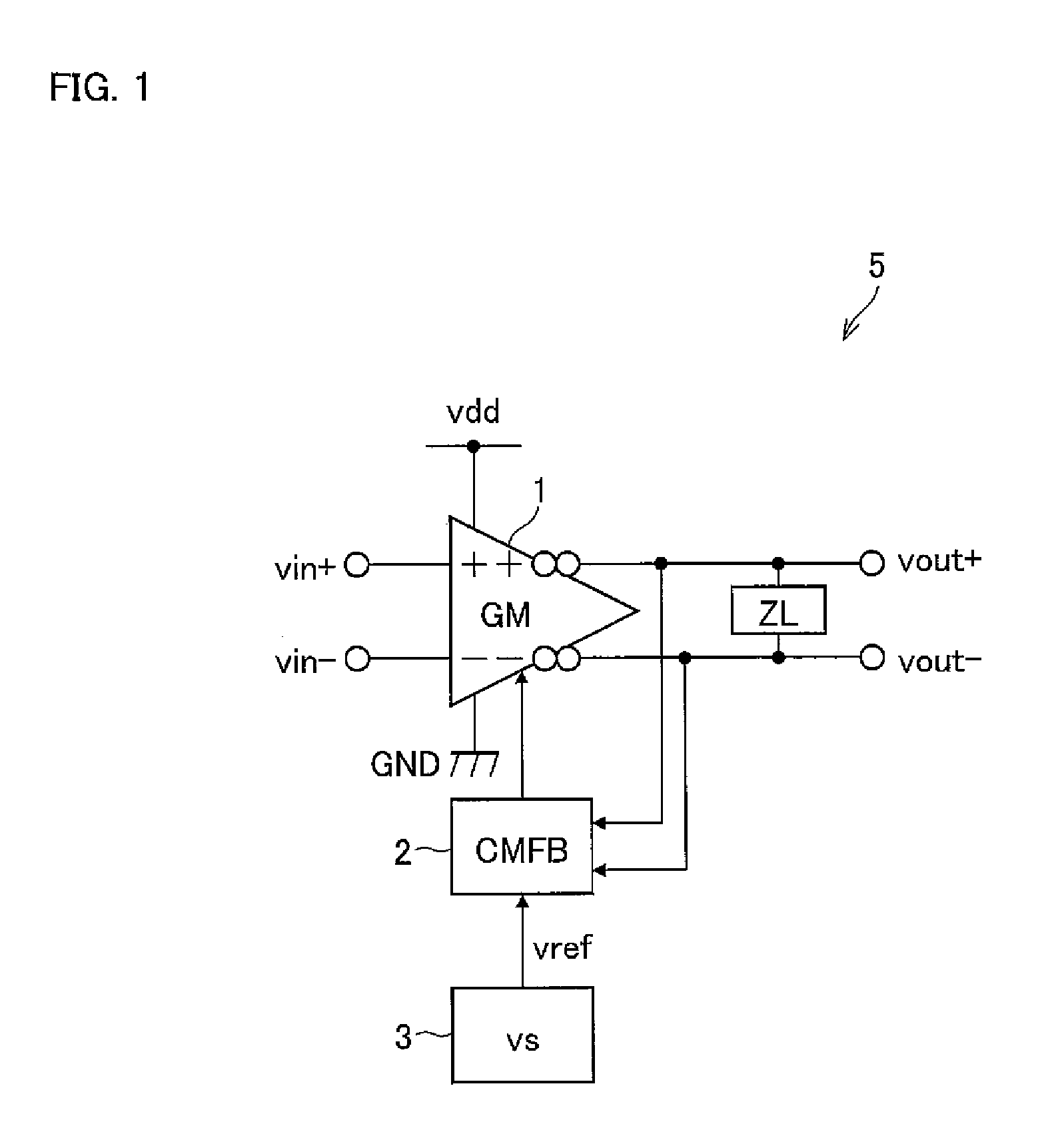
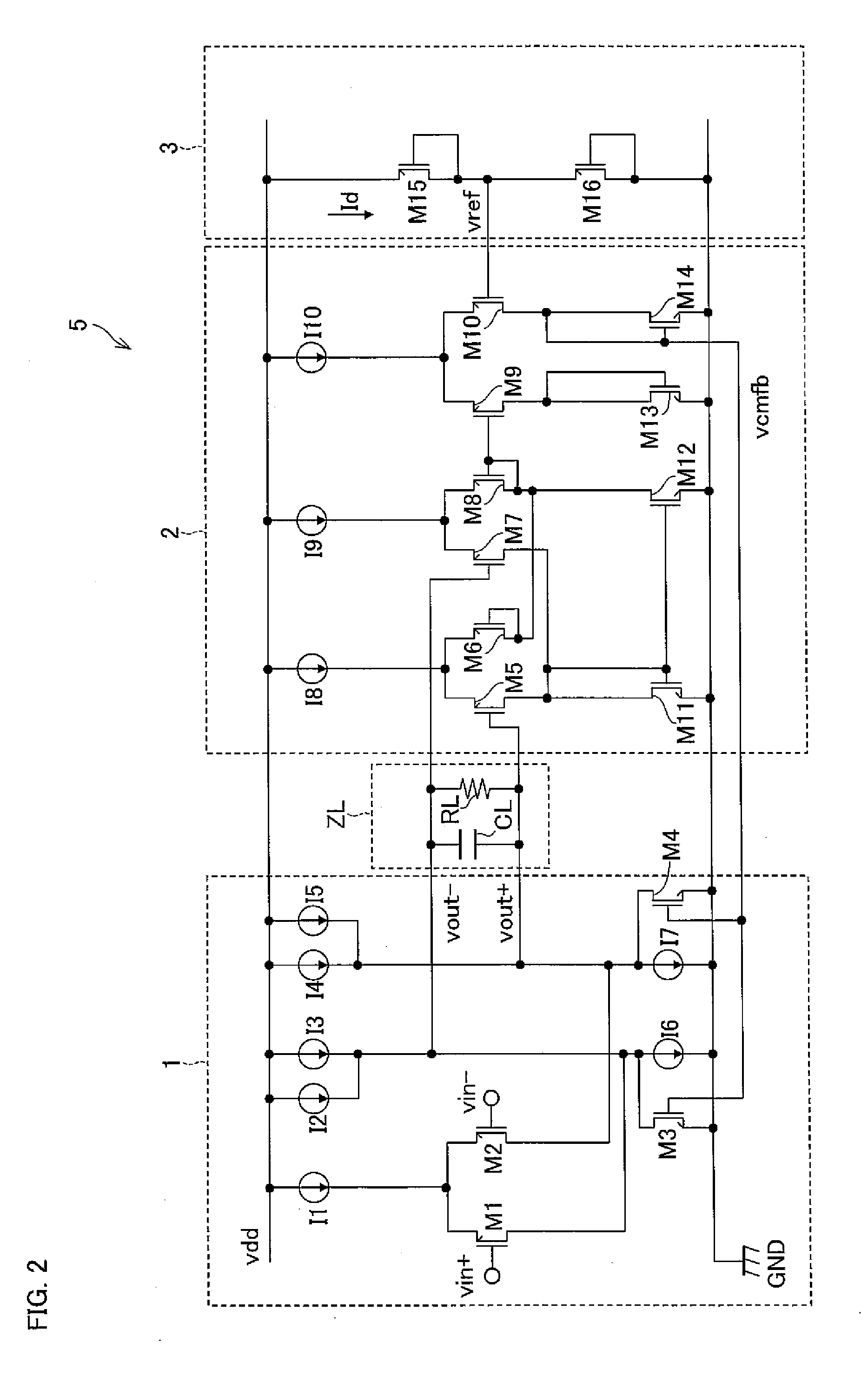
[0068]FIG. 1 shows a configuration of an operational amplifier circuit 5.
[0069]The operational amplifier circuit 5 includes: a transconductance amplifier circuit (hereinafter simply referred to as GM) 1 which converts a differential input voltage into a differential output current; an output load ZL to which a differential output voltage of the GM1 is applied and which constitutes an output terminal of the operational amplifier circuit 5; a common-mode feedback circuit (hereinafter simply referred to as CMFB) 2 to which the differential output voltage of the GM1 and a reference voltage vref are input, and which outputs a control signal to the GM1 so that a D.C. voltage level of the differential output voltage of the GM1 equals the reference voltage vref; and a voltage supply circuit (VS) 3 which supplies the reference voltage vref to the CMFB2. An input terminal of the operationa...
embodiment 2
[0136]An embodiment of the present invention is described below with reference to FIG. 4 to FIG. 7.
[0137]FIG. 4 shows a configuration of a bandpass filter circuit (hereinafter BPF) 20.
[0138]The BPF 20 is a full-differential bandpass filter circuit including: transconductance amplifier circuits (hereinafter, simply referred to as GMs) 11 to 13 (first to third transconductance amplifier circuits) for converting a differential input voltage into a differential output current; common-mode feedback circuits (hereinafter, simply referred to as CMFBs) 14 and 15 (first and second common-mode feedback circuits); capacitors C11 to C13 (first capacitor to third capacitor); and a voltage supply circuit 3 of the foregoing Embodiment 1. Hereafter, the GM11 to GM13 are sometimes referred to as GM, collectively. Further, no explanation for the voltage supply circuit 3 is provided here, as it is already explained in Embodiment 1.
[0139]A noninverting output section of the GM11 is connected to a nonin...
embodiment 3
[0233]The following describes another embodiment of the present invention with reference to FIG. 8 to FIG. 16.
[0234]The present embodiment deals with an infrared remote control receiver (infrared signal processing circuit) (transmission rate=1 kbps or less, spatial transmission distance=10 m or longer) having a BPF of the present invention. Here, the infrared remote control receiver has functions such as a function to reduce inverter fluorescent light noise, a function to reduce distortion in the waveform of an output from the BPF, or the like.
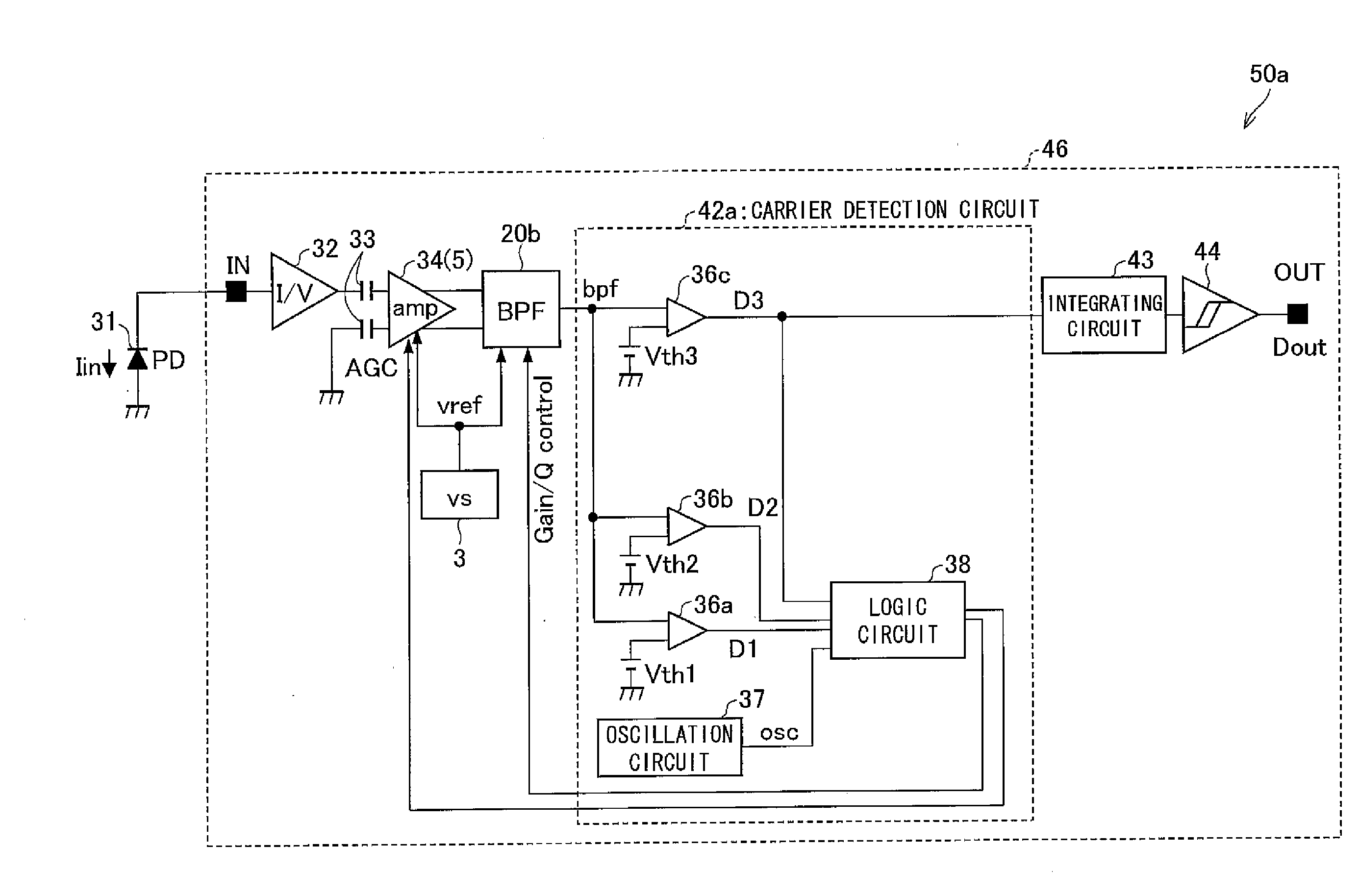
[0235]As an example of such an infrared remote control receiver, FIG. 8 shows a configuration of an infrared remote control receiver 50a.
[0236]An infrared remote control receiver 50a includes a photodiode chip 31 (photo-acceptance element) and a reception chip 46. The reception chip 46 includes: a current-to-voltage-conversion circuit 32; a capacitor 33; an amplifier (amplifying circuit) 34; the BPF 20b (as an example); a carrier detection ci...
PUM
 Abstract
Description
Claims
Application Information