Bandpass filter circuit, band-elimination filter circuit, infrared signal processing circuit

Active Publication Date: 2008-05-15
SHARP KK
View PDF12 Cites 21 Cited by
  • Summary
  • Abstract
  • Description
  • Claims
  • Application Information

AI Technical Summary

Benefits of technology

[0045]It is an object of the present invention to realize a bandpass filter circuit and a band-elimination filter circuit each capable of adjusting a constant such as a Q-value. It is also an object of the present invention to rea

Problems solved by technology

In worst situation, the infrared remote control receiver 110 may not be able to accurately receive signals transmitted from the remote control.
However, raising of the Q-value of the BPF 104 causes distortion in a waveform of the BPF 104 and an increase in the pulse width.
As shown in the figure, the digital output Dout is not properly output due to the distortion in the waveform of the output from the BPF 104, and the reception sensitivity is deteriorated.
In an infrared remote control receiver supportin

Method used


Image

  • Bandpass filter circuit, band-elimination filter circuit, infrared signal processing circuit
  • Bandpass filter circuit, band-elimination filter circuit, infrared signal processing circuit
  • Bandpass filter circuit, band-elimination filter circuit, infrared signal processing circuit

Examples


embodiment 1

[0164]An embodiment of the present invention is described below with reference to FIG. 1 to FIG. 5.

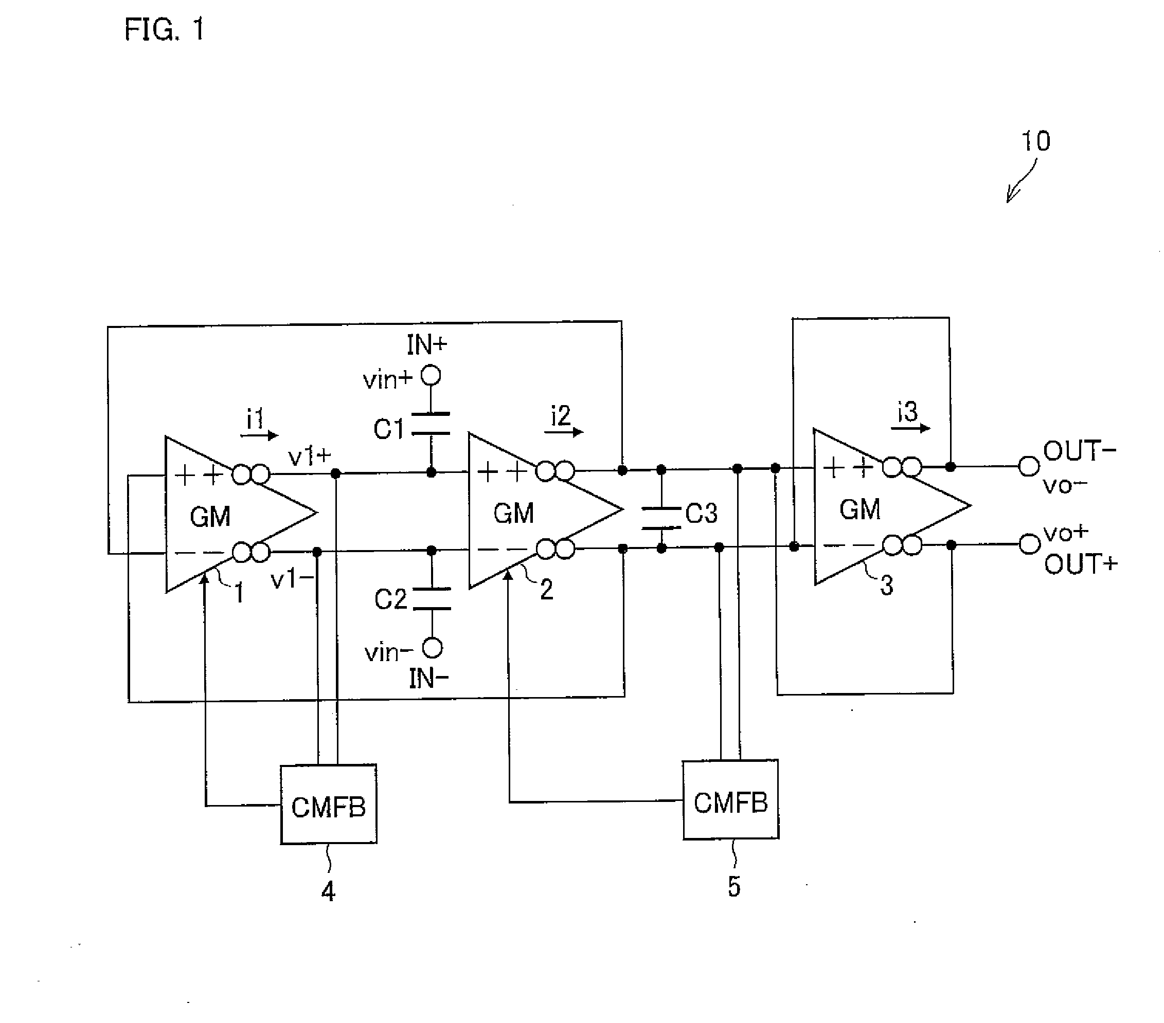
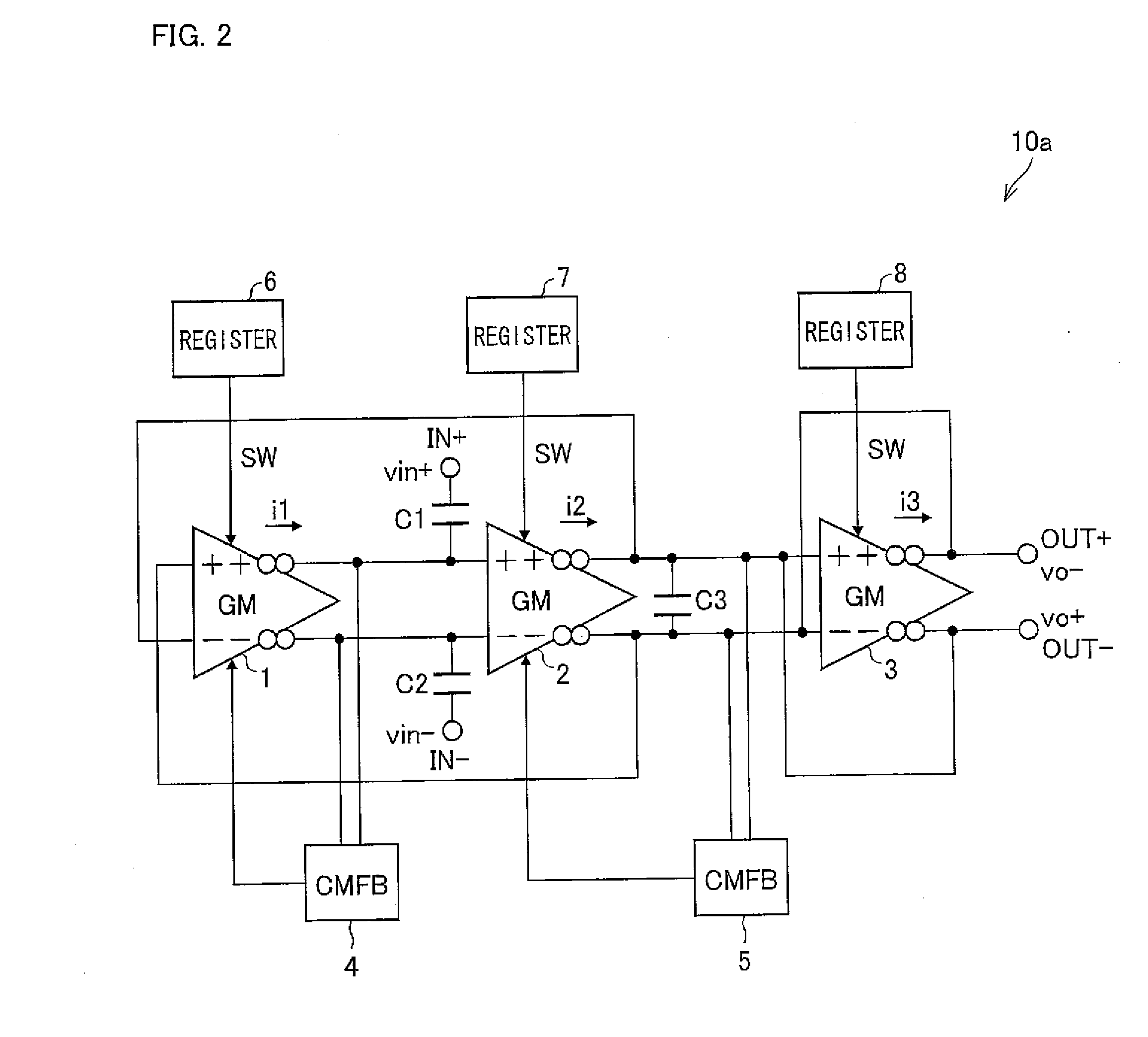
[0165]FIG. 1 shows a configuration of a bandpass filter circuit (BPF) 10 (hereinafter, first bandpass filter circuit).

[0166]The BPF 10 is a full-differential bandpass filter circuit including: transconductance amplifier circuits (hereinafter, simply referred to as GMs) 1 to 3 (first transconductance amplifier to third transconductance amplifier) for converting a differential input voltage into a differential output current; common-mode feedback circuits (hereinafter, simply referred to as CMFBs) 4 and 5 (first and second common-mode feedback circuits); and capacitors C1 to C3 (first capacitor to third capacitor). Hereafter, the GM1 to GM3 are sometimes referred to as GM, collectively.

[0167]A noninverting output section of the GM1 is connected to a noninverting input section of the GM2, and an inverting output section of the GM1 is connected to an inverting input section of the GM2. A n...

embodiment 2

[0267]The following describes another embodiment of the present invention with reference to FIG. 6 to FIG. 8.

[0268]FIG. 6 shows a configuration of a band-elimination filter circuit (band-elimination circuit; hereinafter, BEF) 25 (first band-elimination filter circuit).

[0269]The BEF 25 is a full-differential band-elimination filter circuit including: transconductance amplifier circuits (hereinafter simply referred to as GMs) 11 to 14 (first transconductance amplifier to fourth transconductance amplifier) each for converting a differential input voltage into a differential output current; first and second common-mode feedback circuits (hereinafter, simply referred to as CMFB) 15 and 16 (first and second common-mode feedback circuits); and capacitors C11 to C13 (first to third capacitors). Hereafter, the GM11 to GM14 are sometimes referred to as GM, collectively.

[0270]A noninverting input terminal IN+ of the BEF 25 is connected to a noninverting input section of the GM11. An inverting ...

embodiment 3

[0315]Another embodiment of the present invention is described below with reference to FIG. 9 to FIG. 16.

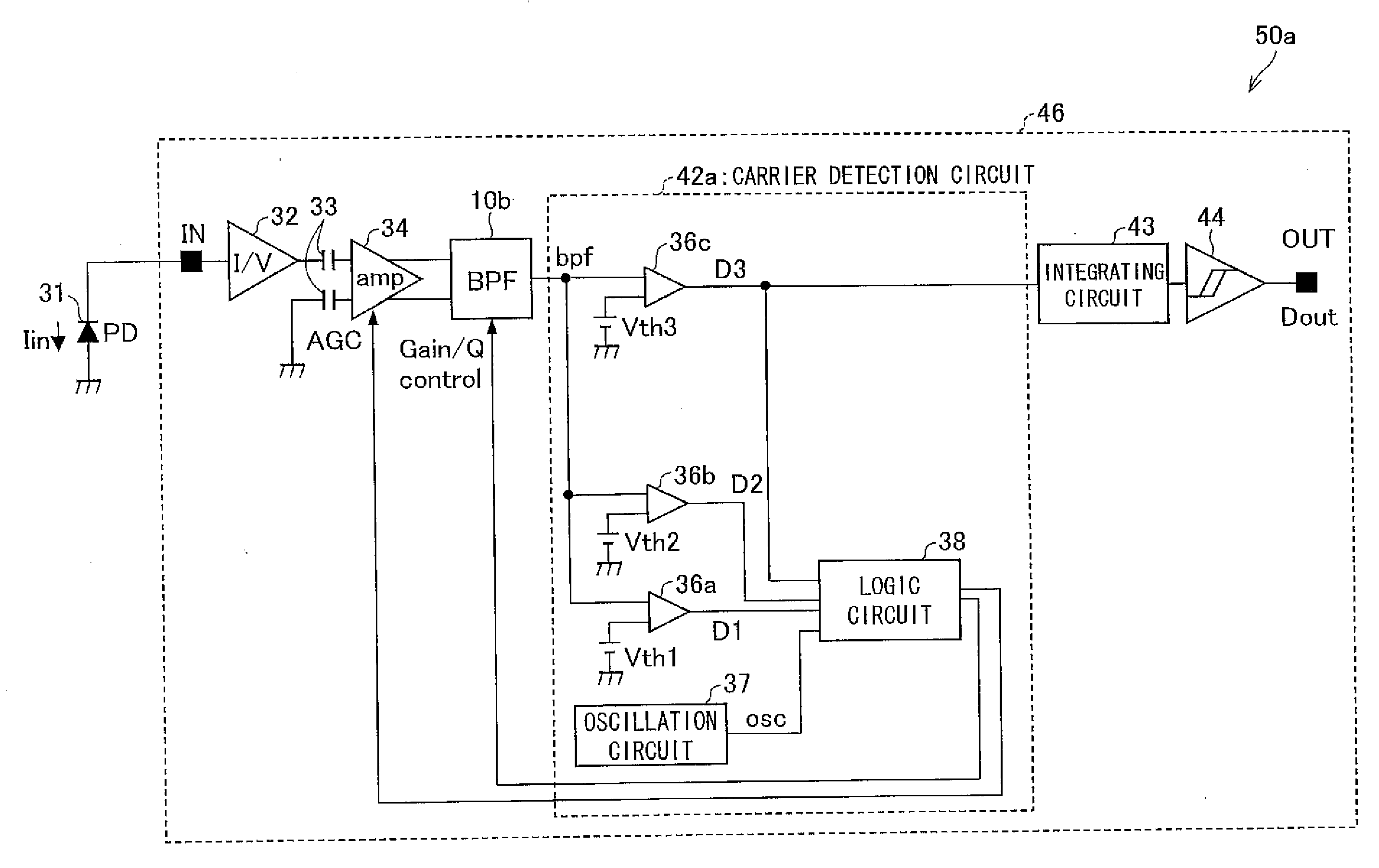
[0316]As mentioned above, a BPF of the present invention allows adjustment of its constant such as the Q-value and the gain H by means of adjusting the gm. In the present embodiment, such a BPF of the present invention is adopted to an infrared remote control receiver (infrared signal processing circuit )(transmission rate 1 kbps or less, spatial transmission distance 10 m or longer) which is capable of (i) reducing noise stemming from an inverter fluorescent light and (ii) reducing distortion in the waveform of an output from the BPF.

[0317]As an example of such an infrared remote control receiver, FIG. 9 shows a configuration of an infrared remote control receiver 50a.

[0318]An infrared remote control receiver 50a includes a photodiode chip 31 (photo-acceptance element) and a reception chip 46. The reception chip 46 includes: a current-to-voltage-conversion circuit 32; a capacit...


PUM


Abstract

A bandpass filter circuit 10 of the present invention includes: transconductance amplifier circuits 1 to 3; a common-mode feedback circuit 4 which outputs a first control signal to the transconductance amplifier circuit 1 so that a D.C. voltage level of a differential output of the transconductance amplifier circuit 1 is at a predetermined level; a common-mode feedback circuit 5 which outputs a second control signal to the transconductance amplifier circuit 2 so that a D.C. voltage level of a differential output of the transconductance amplifier circuit 2 is at a predetermined level; and capacitors C1 to C3. Each of the members are connected as shown in FIG. 1. With the configuration, a bandpass filter circuit capable of adjusting constants such as a Q-value is realized.

Description

[0001]This Nonprovisional application claims priority under 35 U.S.C. §119(a) on Patent Application No. 309630 / 2006 filed in Japan on Nov. 15, 2006, the entire contents of which are hereby incorporated by reference.FIELD OF THE INVENTION[0002]The present invention relates to a bandpass filter ciruit and a band-elimination filter circuit with an improved power-source noise canceling characteristic, each of which circuit is capable of adjusting a constant such as a Q-value. Further, the present invention also relates to an infrared signal processing circuit, having the bandpass filter circuit, which is capable of reducing distortion in a waveform output from the bandpass filter circuit while reducing disturbance light noise.BACKGROUND OF THE INVENTION[0003]Typical examples of an infrared signal processing circuit are: remote controllers of home electric appliances and peripheral devices of personal computers, each of which performs data communication in compliance with IrDA (Infrared ...

Claims


Application Information

Patent Timeline
IPC IPC(8): H04B10/06H03H11/12H03G3/10H03H11/04H04B10/00H04B10/2507
CPCH03F3/087H03F3/45183H03F3/45475H03F3/45636H03F3/45932H03F2203/45101H03K2005/00208H03H11/0433H03H11/0455H03H11/0472H03K3/0231H03K3/0322H03K2005/00071H03F2203/45138
Inventor INOUE, TAKAHIRO
Owner SHARP KK
Why Eureka
Try Eureka