
Silt fence apparatus and method of construction

a technology of silt fences and fences, applied in foundation engineering, excavations, construction, etc., can solve the problems of large areas of soil mounds which may lay undisturbed for several months, severe run-off, contaminating streams, etc., and achieves less subject matter, less strength, and more economical construction and maintenance.

Inactive Publication Date: 2008-05-15
KERMAN MICHAEL LEWIS
View PDF10 Cites 12 Cited by
  • Summary
  • Abstract
  • Description
  • Claims
  • Application Information

AI Technical Summary

Benefits of technology

[0015] The present invention relates to an improvement in the manner of securing the flexible plastic silt fencing material to a fence post or stake which provides a silt fence which is desirable, maintenance free, less subject to damage due to wind conditions, and much more economical to build and maintain. The invention completely avoids the shortcoming of the mechanical methods of attachment (i.e. staples, hog rings, nailing, or sandwiching between posts, etc.) where strength reduction is caused by the penetrating, cutting, tearing, breaking or thinning of the silt screen material or reinforcement surfaces due to the attachment procedure used.
[0019] The bonding of the stakes to the silt screen with or without the reinforcement member is accomplished by the use of a hot melt adhesive, when using an adhesive that has a surface tension lower than the surface tension of the outer surface of the stake members. The bonding is almost instantaneous and requires just a few seconds of time to cure so that the technique of manufacturing by rolling the silt screen, with or without the reinforcement member upon an attached stake and winding the silt screen material upon itself with additional stakes bonded at preselected intervals, can be a continuous process because the hot melt adhesive requires a very short curing period. The curing of the molecular bond is almost instantaneous.
[0022] It is a further primary object of the invention to provide a silt fencing system which can be readily installed so that its effectiveness in impeding the flow of ground water to minimize the run-off of the silt and soil is readily utilized.
[0023] It is a further object of the invention to provide a silt fence which includes means for securely mounting the web to the stakes without the reduction of the strength of the web by penetrating, cutting, breaking, or thinning the silt screen web or reinforcing material.
[0024] It is yet a further object of the invention to provide a silt fence wherein the web may be mounted to the stakes in a simple and economical manner.

Problems solved by technology

In excavating and grading work, such as in the construction of golf courses, highways, shopping centers, or other commercial and residential construction, the work often results in large areas of mounds of soil which may lay undisturbed for several months until the project is completed and graded.
Often, these areas are subjected to severe weather conditions such as rain or storms resulting in severe run-off as a result of the surface water carrying the soil to various unwanted areas.
The run-off will often block drains, as in a subdivision, contaminate streams as in the construction of golf courses as well as ponds, and kill vegetation, depending on the flow of the run-off and the length of time such action occurs.
However, the time it takes to seed the area and grow appropriate vegetation to contain or prevent the run-off is often long term and under the present environmental regulations, run-off during the period of time that it takes to grow the vegetation is generally not acceptable.
Temporary seeding is also an unneeded expense.
This form of solution is strictly temporary since water will find new paths and the problem will often reappear shortly after the bales of straw have resided in one place for a period of time.
Wright further points out that conventional means of securement is unsatisfactory whereby fasteners and staples are used because the staples tend to tear through the fabric web when exposed to environmental conditions such as high winds, snow drifts, and the like.
Further, where fasteners are used, the puncturing of the material by the fastener tends to provide a weak point where tears and holes are started and continue as a result of environmental conditions.

Method used


Image

  • Silt fence apparatus and method of construction
  • Silt fence apparatus and method of construction
  • Silt fence apparatus and method of construction

Examples


Embodiment Construction

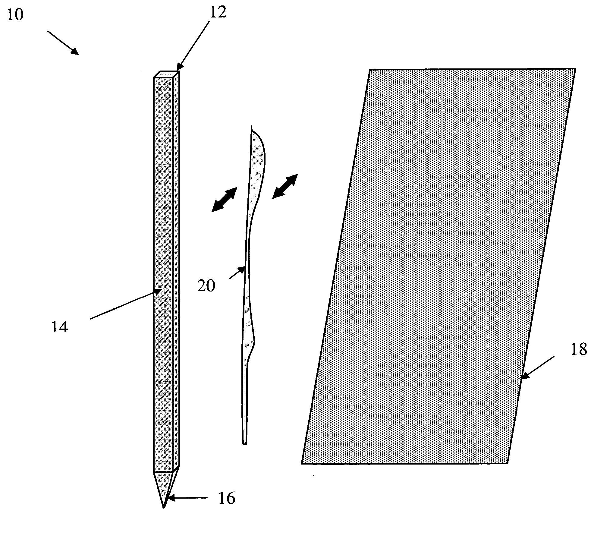
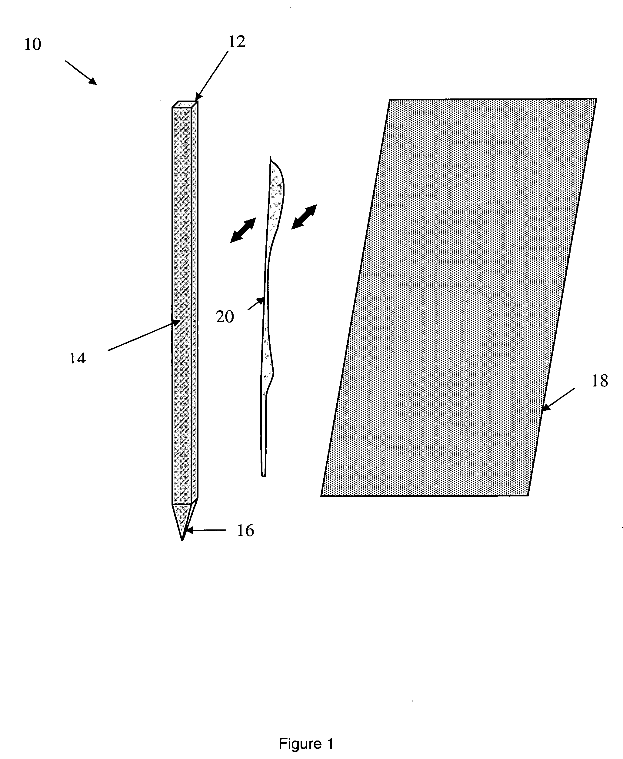
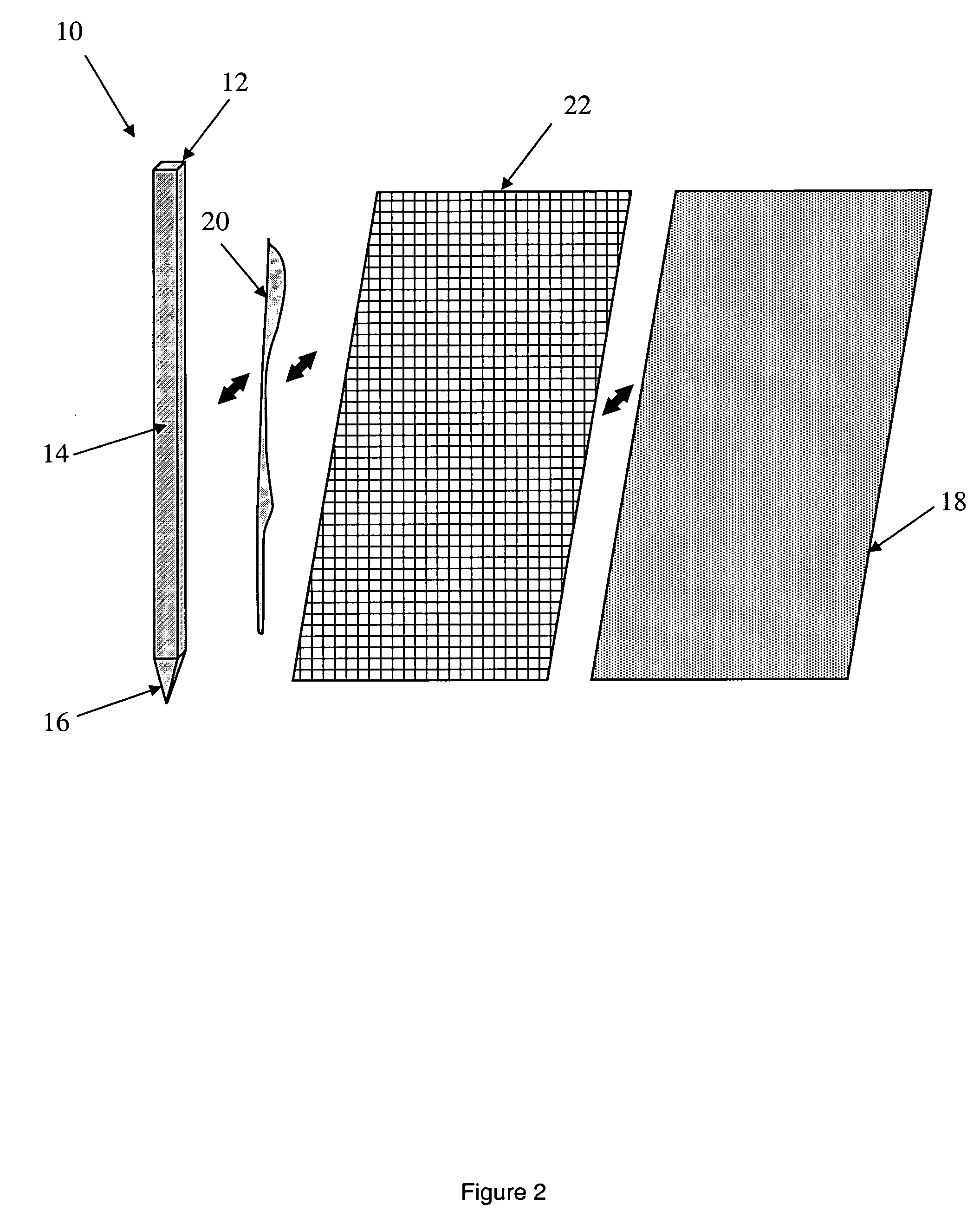
[0031]FIGS. 1-4 illustrate a silt fence assembly 10 in accordance with the invention. The silt fence assembly 10 includes a plurality of support stakes 12, preferably made from plastic, each of which consists of a longitudinal body portion 14 terminating in a pointed end 16 so that the pointed end 16 may be penetrated into the ground surface for anchoring the plurality of support stakes 12 in an upright position. Although the preferred embodiment is a plastic material for the support stake 12, it is understood that the support stake 12 may be fabricated of any plastic, metal, wood, or wood composite material or size of any convenient cross-section as dictated by the specific application.

[0032] As also illustrated in FIGS. 1-4, the silt fence assembly 10 includes a web or silt fabric screen 18 of any suitable woven polymeric fabric. Woven silt fabrics using synthetic yarns have been used increasingly in recent years to prevent soil run-off at construction sites. These fabrics are ge...


PUM


Abstract

The invention is a silt screen fence assembly which combines the use of a polymeric silt screen fabric with or without a plastic reinforcement member and a thermoplastic support stake with a hot melt adhesive to attach the silt screen fabric with or without the reinforcement member to the support stake to provide an extremely durable and tenacious bond of the screen fabric to the support stake so as to overcome the inherent problems with prior art silt screen fences wherein the mechanical bond is initially significantly weakened due to penetrating, cutting, punching, or thinning out the silt screen or reinforcement material upon assembly.

Description

CROSS-REFERENCE TO RELATED APPLICATIONS [0001] This application is a continuation-in-part of U.S. patent application Ser. No. 11 / 724,876, filed on Mar. 16, 2007 which claims the benefit of U.S. Provisional Patent Application Ser. No. 60 / 783,562, filed on Mar. 17, 2006.FEDERALLY SPONSORED RESEARCH OR DEVELOPMENT [0002] Not applicable. REFERENCE TO A SEQUENCE LISTING [0003] Not applicable. BACKGROUND OF THE INVENTION [0004] 1. Field of the Invention [0005] The present invention relates generally to a system for minimizing erosion of a site of soil, more particularly, the invention pertains to the provision of a material and system for minimizing the erosion of soil during a construction period. [0006] 2. Description of the Related Prior Art [0007] In excavating and grading work, such as in the construction of golf courses, highways, shopping centers, or other commercial and residential construction, the work often results in large areas of mounds of soil which may lay undisturbed for ...

Claims


Application Information

Patent Timeline
Patent Type & Authority Applications(United States)
IPC IPC(8): E02D3/00
CPCE02D17/20
Inventor KERMAN, MICHAEL LEWIS
Owner KERMAN MICHAEL LEWIS
Learn More