Lens Barrel, Camera and Mobile Information Terminal

a technology of mobile information terminal and lens barrel, which is applied in the direction of mountings, printing, instruments, etc., can solve the problems of difficult to reduce the entire thickness of the lens unit including the five lens groups, the lens unit is not suitable for miniaturization of the lens unit, and the lens barrel has a large diameter

Active Publication Date: 2008-05-22
RICOH KK
View PDF8 Cites 26 Cited by
  • Summary
  • Abstract
  • Description
  • Claims
  • Application Information

AI Technical Summary

Benefits of technology

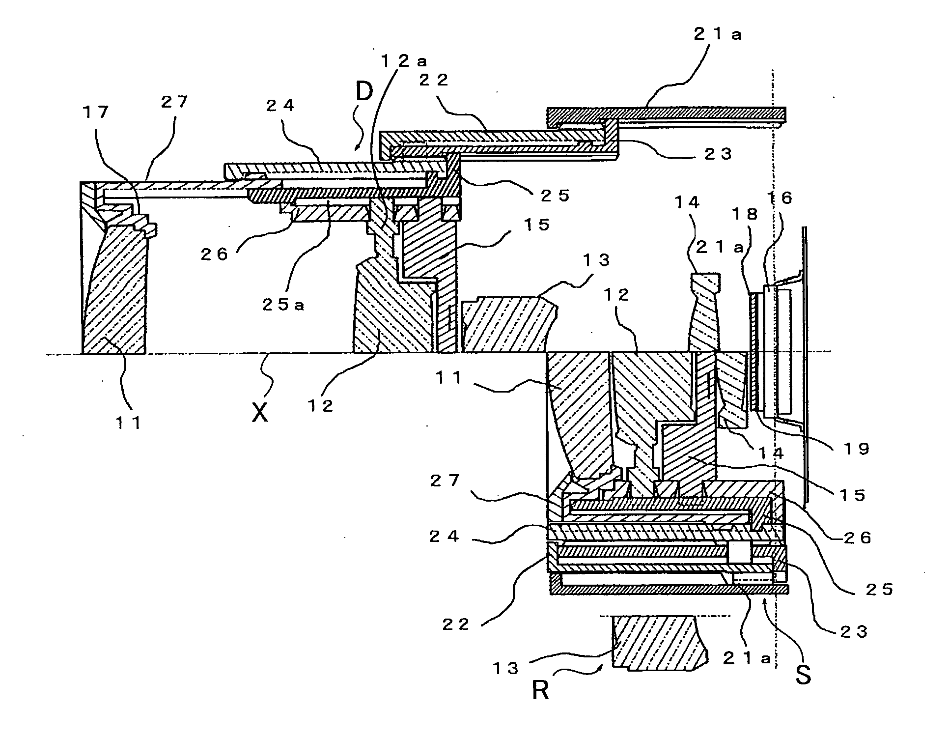
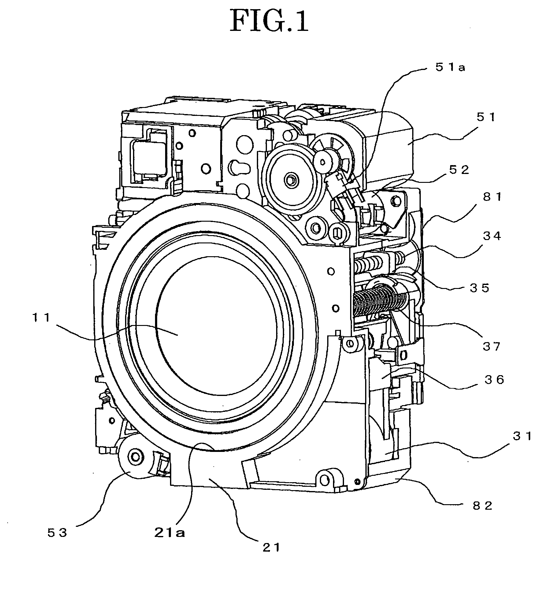
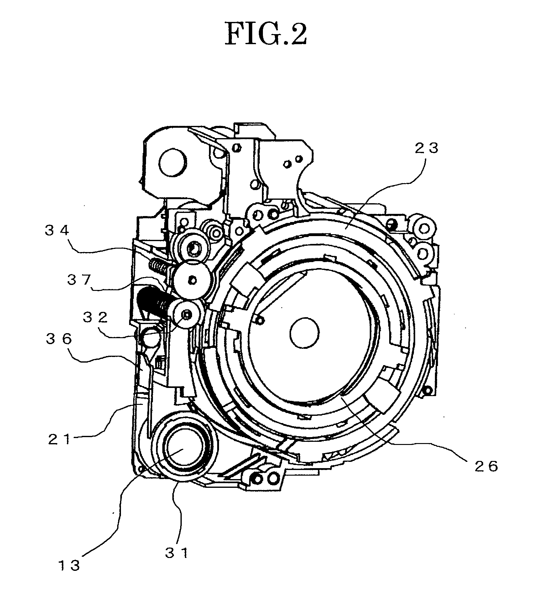
[0037]An object of the present invention is to provide a lens barrel capable of minimizing a dimension in a direction of an optical axis of lens groups when the lens groups are collapsed, and a dimension in a plane transverse to the optical axis, and a camera using the lens barrel and a portable information terminal using the lens barrel.
[0040]Another object of the present invention is to provide a compact lens barrel having a great changing magnification ratio.

Problems solved by technology

Accordingly, there is a problem that the conventional lens barrel has a large diameter by provision of the space containing the retracted lens in the lens barrel.
Although various zoom lens units for digital cameras are used, it is difficult to decrease the entire thickness of a lens unit including five lens groups or more, the lens unit is not suitable for miniaturization of the lens unit.
However, such a zoom lens unit is not suitable for a high changing magnification ratio structure having four (4) times or more.
Therefore, there is a problem that the first lens group becomes a very large size when a wide angle is provided.
However, in the zoom lens unit disclosed in these patent documents, the semi-field angle at the wide angle position is limited to about 25 to 32 degrees, the wide angle is still insufficient.
In realizing such a wide field angle, off-axis aberration such as distortion aberration, chromatic aberration of magnification or the like is easy to often generate, hence a lens design is very difficult in cooperation with the fact that the pixel pitch of the image-sensing device is less.
Therefore, the conventional zoom lenses cannot respond to the recent request for the higher performance satisfying both the wider field angle and the high changing magnification ratio.

Method used


Image

  • Lens Barrel, Camera and Mobile Information Terminal
  • Lens Barrel, Camera and Mobile Information Terminal
  • Lens Barrel, Camera and Mobile Information Terminal

Examples


embodiment 1

[0377]Next, specific embodiments will be described in detail based on the above embodiment of the present invention. The following embodiments 1, 2, 3, 4 are the embodiments specifically structured by the specific numerical examples of the zoom lenses according to the present invention. The embodiment 5 is the specific embodiment of the camera or the mobile information terminal according to the present invention using the lens unit comprising the zoom lens as described in the embodiments 1 to 4 as the optical system for photographing.

[0378]The embodiments 1 to 4 of the zoom lenses according to the present invention indicate the structures of the zoom lenses and the specific numeral examples. In addition, in the embodiments 1 to 4, the maximum image height is 3.70 mm.

[0379]In each of the embodiments 1 to 4, an optical element comprising a parallel plate disposed on the image side of the fourth lens group assumes various types of optical filters such as an optical lowpass filter and i...

embodiment 2

[0405]FIGS. 30A, 30B, 30C show the structures of the optical systems of the zoom lenses according to the embodiment 2 of the present invention. FIG. 30A illustrates the wide angle position (short focal length position). FIG. 30B illustrates the intermediate focal length. FIG. 30C illustrates the telephoto position (long focal length position).

[0406]The zoom lens illustrated in each of FIGS. 30A, 30B, 30C includes a first lens E1, second lens E2, third lens E3, fourth lens E4, fifth lens E5, sixth lens E6, seventh lens E7, eighth lens E8, ninth lens E9, aperture stop FA and filter / cover FC. In this case, a first lens group G1 comprises the first lens E1 and second lens E2. A second lens group G2 comprises the third lens E3, fourth lens E4 and fifth lens E5. A third lens group G3 comprises the sixth lens E6, seventh lens E7 and eighth lens E8. A fourth lens group G4 comprises the ninth lens E9. Each lens group is supported by an appropriate common supporting frame and the like, and is...

embodiment 3

[0423]FIGS. 31A, 31B, 31C show structures of the optical systems of the zoom lenses according to the embodiment 3 of the present invention. FIG. 31A illustrates the wide angle position (short focal length position). FIG. 31B illustrates the intermediate focal length. FIG. 31C illustrates the telephoto position (long focal length position).

[0424]The zoom lens illustrated in each of FIGS. 31A, 31B, 31C comprises a first lens E1, second lens E2, third lens E3, fourth lens E4, fifth lens E5, sixth lens E6, seventh lens E7, eighth lens E8, ninth lens E9, tenth lens E10, aperture stop FA and filter / cover FC. In this case, a first lens group G1 comprises the first lens E1, second lens E2 and third lens E3. A second lens group G2 comprises the fourth lens E4, fifth lens E5 and sixth lens E6. A third lens group G3 comprises the seventh lens E7, eighth lens E8 and ninth lens E9. A fourth lens group G4 comprises the tenth lens E10. Each of the lens groups is supported by an appropriate common ...


PUM


Abstract

A lens barrel including a telescopic cylinder configured to be accommodated within a fixed frame; a plurality of lens groups configured to be retained in the telescopic cylinder; a lens driving device configured to drive the plurality of lens groups along a longitudinal axis of the telescopic cylinder between a collapsed position in which at least one portion of the plurality of lens groups is stored in the fixed frame and an extended position in which the at least one portion of the plurality of lens groups is extended out of the fixed frame; and a retractable lens group configured to be retracted into the fixed frame through an opening in a wall of the fixed frame when the telescopic cylinder is in the extended position.

Description

CROSS-REFERENCE TO RELATED APPLICATIONS[0001]The present application claims the priority benefit of each of Japanese Patent Application 2004-217539 filed on Jul. 26, 2004, Japanese Patent Application 2005-044909 filed on Feb. 22, 2005, and Japanese Patent Application 2005-127226 filed on Apr. 25, 2005. In addition, the present application is related to the U.S. patent application entitled “Lens Barrel, Camera and Portable Information Terminal Device” (Attorney Docket No. 274053US), which claims the benefit of priority to Japanese patent application No. 2004-217924 filed on Jul. 26, 2004. In addition, the present application is related to the U.S. patent application entitled “Lens Barrel, Camera and Portable Information Terminal” (Attorney Docket No. 274052US), which claims the benefit of priority to Japanese Patent Application No. 2004-217927, filed on Jul. 26, 2004. In addition, the present application is related to the U.S. patent application entitled “Optical System Apparatus, Ca...

Claims


Application Information

Patent Timeline
Patent Type & Authority Applications(United States)
IPC IPC(8): G02B15/16G02B7/02G02B7/10
CPCG02B7/021G02B7/022G02B7/102H04M2250/52G03B17/04G03B29/00G02B15/173G02B15/144113G03B30/00G03B5/00G03B17/12G03B2217/005
Inventor NUNO, KATSUHIKOSUGIURA, KOICHIOHASHI, KAZUYASU
Owner RICOH KK
Why Eureka
Try Eureka