
OFDM receivers

a receiver and orthogonal frequency division technology, applied in the field of receiving ofdm signals, can solve the problems of high cost of implementing a system that interpolates by four in the frequency axis and then performs noise reduction filtering in the time axis, and can not meet the requirements of the time axis

Active Publication Date: 2008-05-22
IMAGINATION TECH LTD
View PDF10 Cites 36 Cited by
  • Summary
  • Abstract
  • Description
  • Claims
  • Application Information

AI Technical Summary

Benefits of technology

[0029]Because the relationship defines a diagonal in the n-k plane, the filtering spans both the frequency and time domain. This has been found to produce improved results, for less memory space. Each pilot sub-carrier entered into the m-tap filter satisfies the n-k relationship. Because that relationship defines a diagonal in the n-k plane, the m pilot sub-carriers “surround” the selected pilot sub-carrier along that diagonal line. Preferably, the pilot sub-carriers surround the selected pilot sub-carrier symmetrically i.e. with the same number of pilots either side of the selected pilot.
[0031]By performing the interpolation after the noise has been reduced, the resulting interpolation will be more accurate. The interpolation may be used in a receiver for channel estimation, so a more accurate interpolation will increase accuracy of the channel estimation and hence increase accuracy of the recovered transmitted signal.
[0046]The number of taps m on the filter may be any number, but the larger the number of taps, the better the performance but the larger the memory required for the system. Preferred embodiments of the invention use four six or eight taps for interpolation by four in the time axis, sixteen taps for interpolation by four in the frequency axis, fifteen taps for noise reduction filtering in the frequency axis and fifteen taps for noise reduction filtering in the diagonal axis.
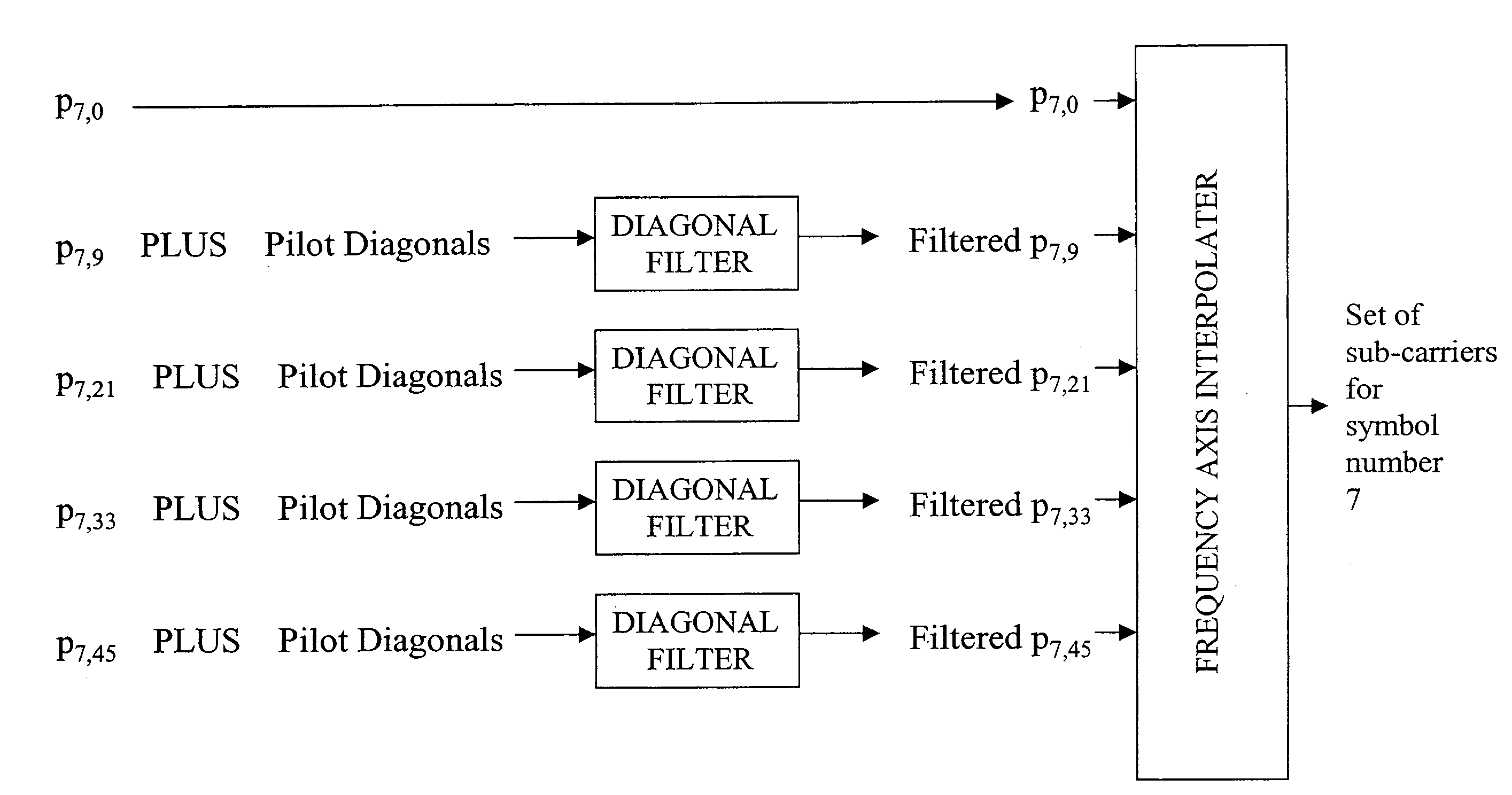
[0052]The apparatus may further comprise a plurality of m-tap filters for producing filtered versions of a plurality of selected pilot sub-carriers. The resulting filter will produce a set of filtered pilot sub-carriers which can be used together for more accurate subsequent interpolation.
[0064]The number of taps m on the filter may be any number, but the larger the number of taps, the better the performance but the larger the memory required for the system. Preferred embodiments of the invention use fifteen taps on the diagonal filter for a system arranged to use four taps on a time interpolation filter, or in general 4.n−1 taps on the diagonal filter for a system arranged to use n taps on a time interpolation filter.

Problems solved by technology

where Tu is the useful symbol duration, the interpolation in the frequency axis will cause aliasing and, as a result, the channel estimation will be inaccurate.
where TS is the total symbol duration, then interpolation in the time axis will cause aliasing and, as a result, the channel estimation will be inaccurate.
The cost of implementing a system that interpolates by four in the frequency axis and then performs noise reduction filtering in the time axis will be very high because either the interpolated virtual pilots must be stored for a number of symbols (for example 16 symbols as shown in FIG. 3), or the virtual pilots must be calculated for a number of symbols (for example 16 symbols as shown in FIG. 3) when the noise reduction filtering for one symbol is performed.
This approach is advantageous in implementation cost, but it cannot work well if the Doppler frequency is so high that time interpolation is inaccurate.
However, apart from the difficulty of estimating these parameters, there are other constraints on the maximum order of these filters and hence the amount of noise attenuation that can be achieved.
Firstly, for frequency axis filtering, the maximum order (m) of the frequency axis filter is constrained by the number of sub-carriers k in the symbol and the difficulty associated at the symbols' upper and lower frequencies (where no further pilot sub-carriers exist).
High order frequency axis filters are also detrimental when narrow-band interferers are present.
The filtering operation causes the interference to be spread across frequency into otherwise unaffected adjacent sub-carriers i.e. the filtering actually increases the amount of interference present.
More memory allows a higher order filter (higher m), but is costly in terms of die area, power consumption and latency.
Some prior art systems filter in the time axis and then filter in the frequency axis, or vice-versa, but this requires a large amount of memory space and processing time.

Method used


Image

  • OFDM receivers
  • OFDM receivers
  • OFDM receivers

Examples


example 1

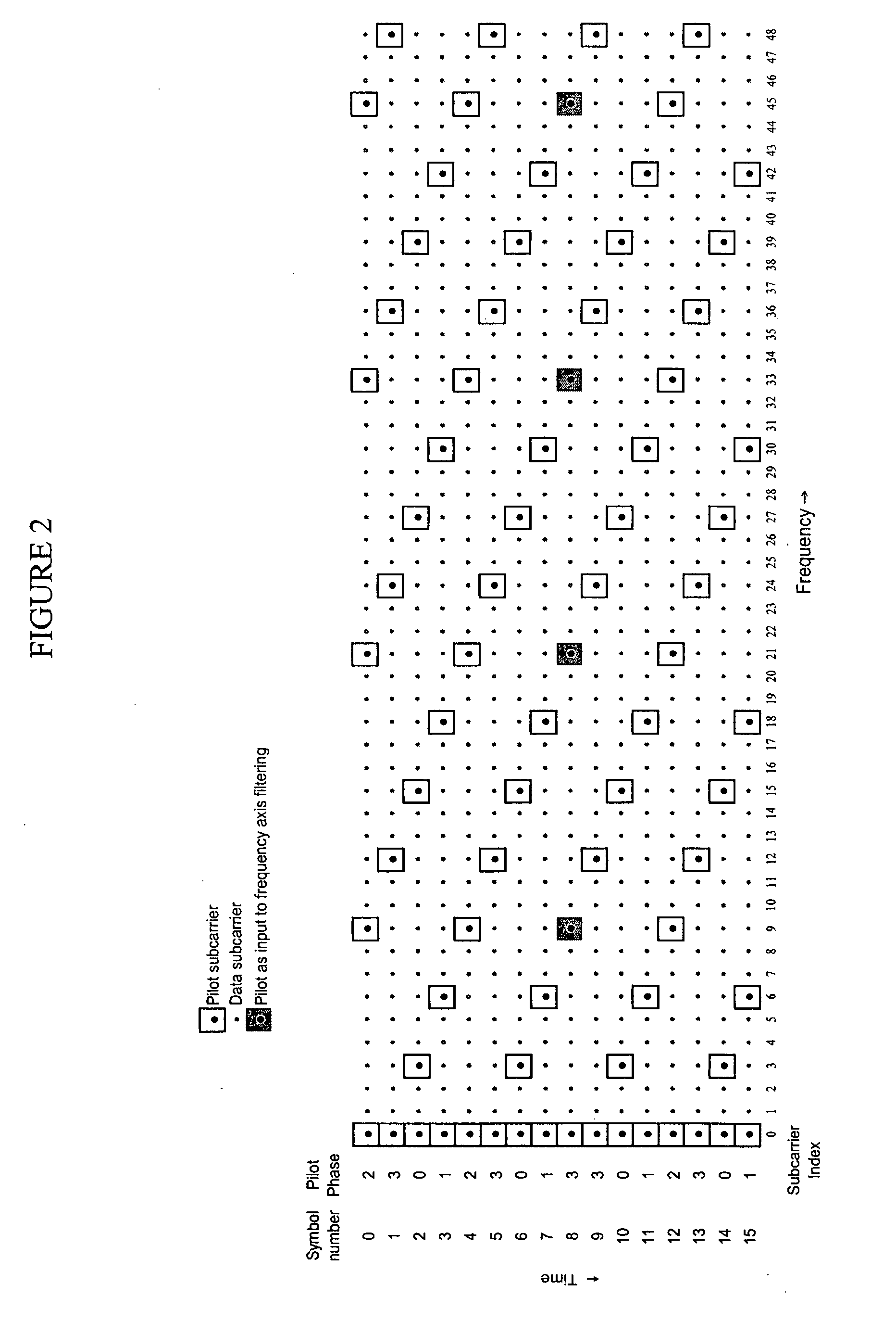
[0128]A specific example of the diagonal filtering as described above will now be described with reference to FIGS. 6 and 7.

[0129]This example shows the application of a 15 tap noise reducing diagonal filter to a channel estimator using frequency axis interpolation.

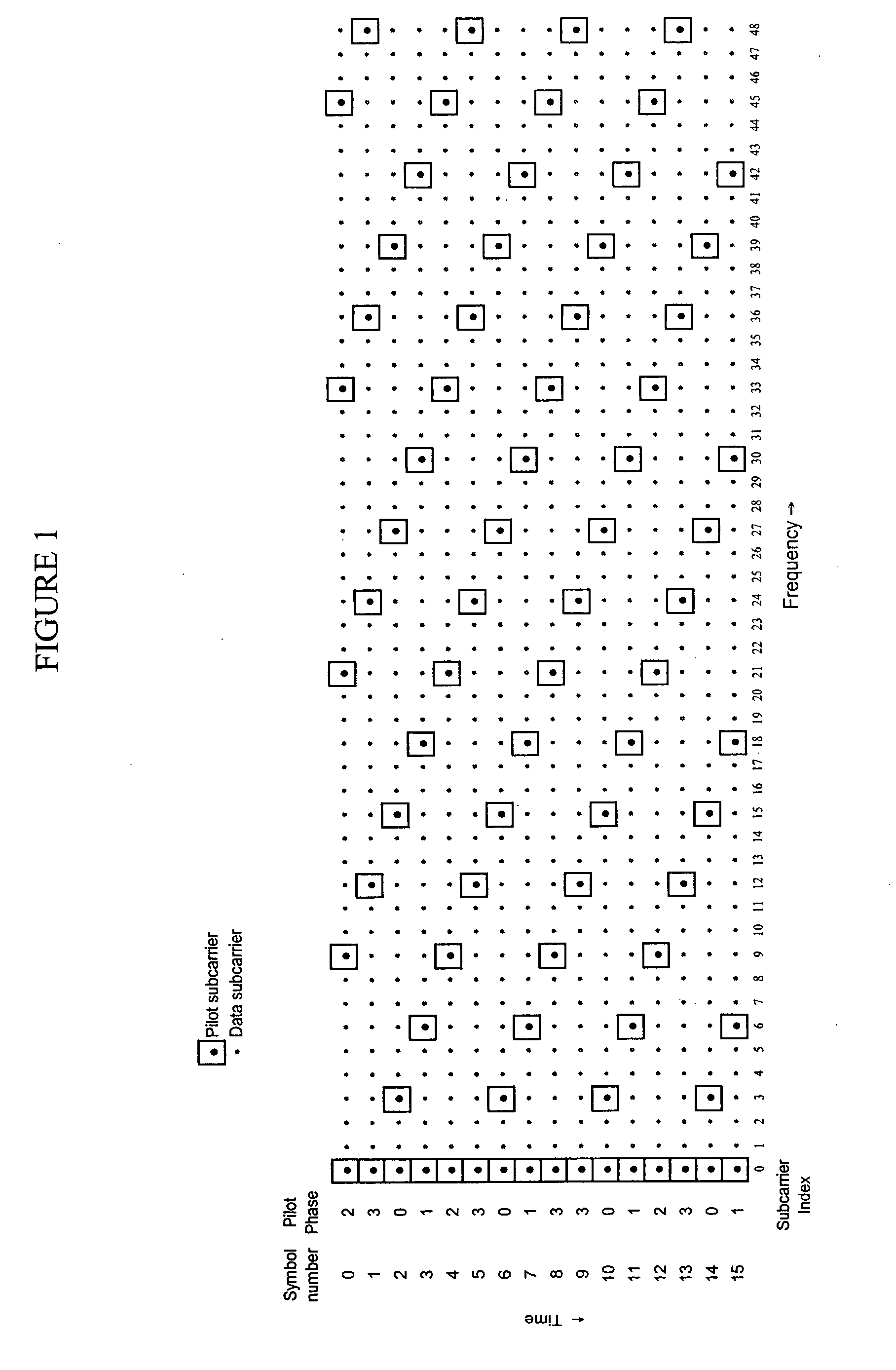
[0130]FIG. 6 shows a subset of the time frequency plane for 16 consecutive OFDM symbols. As in FIGS. 1 to 4, the scattered pilots are highlighted in the diagram. In this example, the channel estimate for symbol number 7 is being estimated (symbol number 0 is the most recently received).

[0131]The channel estimation is performed by interpolating by a factor 12 between the scattered pilot sub-carriers (in this case sub-carriers numbered 0, 9, 21, 33, 45 i.e. those scattered pilots falling within symbol 7). The result is a channel estimate for each of the sub carriers i.e. the band at symbol 7 shown by the dotted lines in FIG. 6. This channel estimate is usually a single complex value per sub-carrier and is used by the equali...

example 2

[0139]A second specific example of the diagonal filtering as described above will now be described with reference to FIGS. 8 and 9.

[0140]This example shows the application of noise reducing diagonal filter to a channel estimator using time axis interpolation.

[0141]FIG. 8 shows a subset of the time frequency plane for 16 consecutive OFDM symbols. As in FIGS. 1 to 5, the scattered pilots are highlighted in the diagram. In this example, the channel estimate for symbol number 7 is being estimated (symbol number 0 is the most recently received).

[0142]In the absence of filtering (i.e. using the raw pilot values), the channel estimate is formed by first interpolating between scattered pilots in the time axis (upsampling by a factor 4) and then using those channel estimates to upsample in the frequency axis (upsampling by a factor 3).

[0143]The interpolation in time would produce all values at every 3rd sub-carrier including channel estimates for p7,0, p7,31, p7,6 and so on. In FIG. 8, the g...


PUM


Abstract

A method and apparatus for filtering a received Orthogonal Frequency Division Multiplexed (OFDM) signal to reduce noise. The ODFM signal includes a plurality of symbols n in the time direction, each symbol including a plurality of sub-carriers k in the frequency direction, each a-th sub-carrier of each symbol being transmitted as a pilot sub-carrier with known amplitude and phase, and each symbol having its pilot sub-carriers spaced by b sub-carriers relative to the adjacent symbol. An m-tap filter is utilized for producing a filtered version of a selected pilot sub-carrier to be used in subsequent interpolation, by inputting into respective taps of the m-tap filter, m pilot sub-carriers surrounding the selected pilot sub-carrier. The m pilot sub-carriers each satisfy a relationship between n and k, wherein the relationship defines a diagonal line in the n-k plane.

Description

FIELD OF THE INVENTION[0001]The invention relates to a method and apparatus for filtering a received OFDM (Orthogonal Frequency Division Multiplexed) signal. Particularly, but not exclusively, the invention relates to receivers for OFDM signals, in particular mobile TV receivers.BACKGROUND OF THE INVENTION[0002]OFDM (Orthogonal Frequency Division Multiplexing) is a transmission scheme used in a number of applications including digital audio broadcasting and digital TV systems (e.g. DVB-T (Digital Video Broadcasting—Terrestrial), DVB-H (Digital Video Broadcasting—Handheld) and ISDB-T (Integrated Services Digital Broadcasting—Terrestrial)).[0003]The bit stream that is to be transmitted is split into several parallel bit streams, typically hundreds or thousands. The available frequency spectrum is split into several channels and each low bit rate stream is transmitted over one channel using some sort of known modulation scheme e.g. QAM (Quadrature Amplitude Modulation) or PSK (Phase Sh...

Claims


Application Information

Patent Timeline
Patent Type & Authority Applications(United States)
IPC IPC(8): H04L27/28
CPCH04L5/0007H04L25/0234H04L25/0226H04L5/0048H04L25/0232H04L27/2647
Inventor ANDERSON, ADRIAN JOHNMURRIN, PAUL DAMON
Owner IMAGINATION TECH LTD
Learn More