
Power generation system driven by heat pump

a technology of power generation system and heat pump, which is applied in the direction of machines/engines, mechanical equipment, lighting and heating apparatus, etc., can solve the problems of increasing the cost of fossilized fuel purchase, the efficiency of stirling heat engine to be less than the heat efficiency of carnot heat engine by 50%, and the cost of mining fossilized fuel. , to achieve the effect of reducing the requirements of fossilized fuel, preventing the generation of green house gases, and effective raising of heat engin

Inactive Publication Date: 2008-06-05
FANG WEI +2
View PDF4 Cites 21 Cited by
  • Summary
  • Abstract
  • Description
  • Claims
  • Application Information

AI Technical Summary

Benefits of technology

[0020]With regard to fore described problems, the present invention brings up a novel power generation system, besides from being able to provide work conditions favorable to heat engine operations but also able to lower requirements of fossilized fuel, reducing release of green house gases.
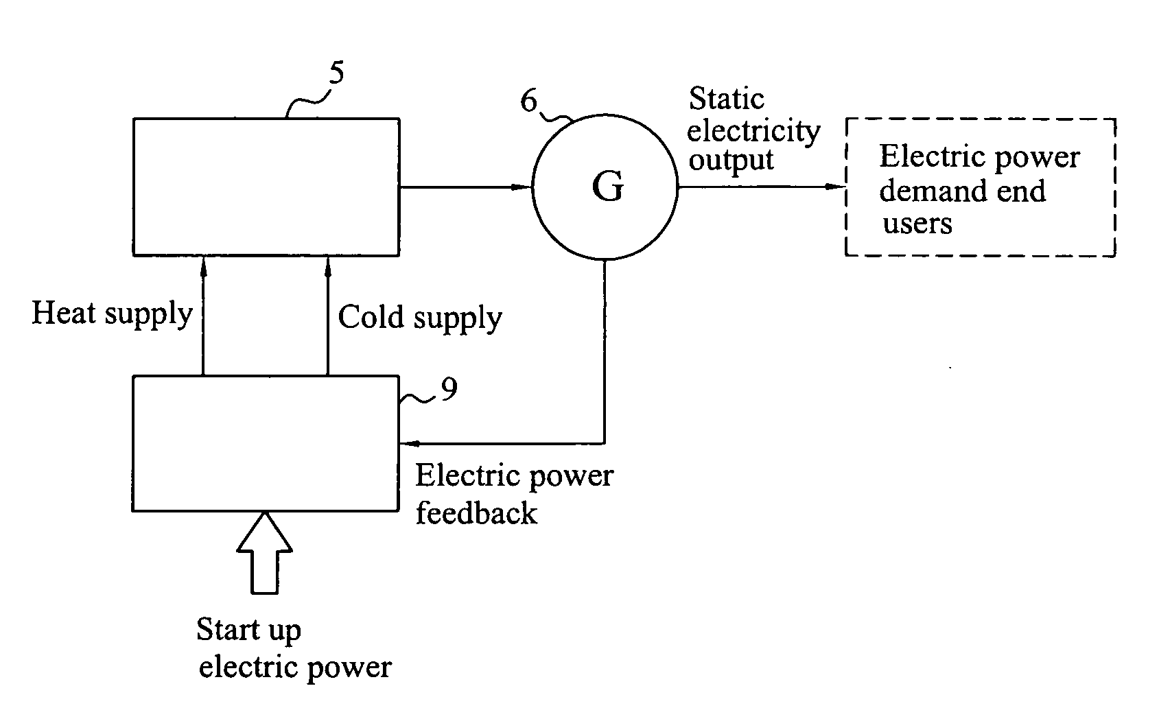
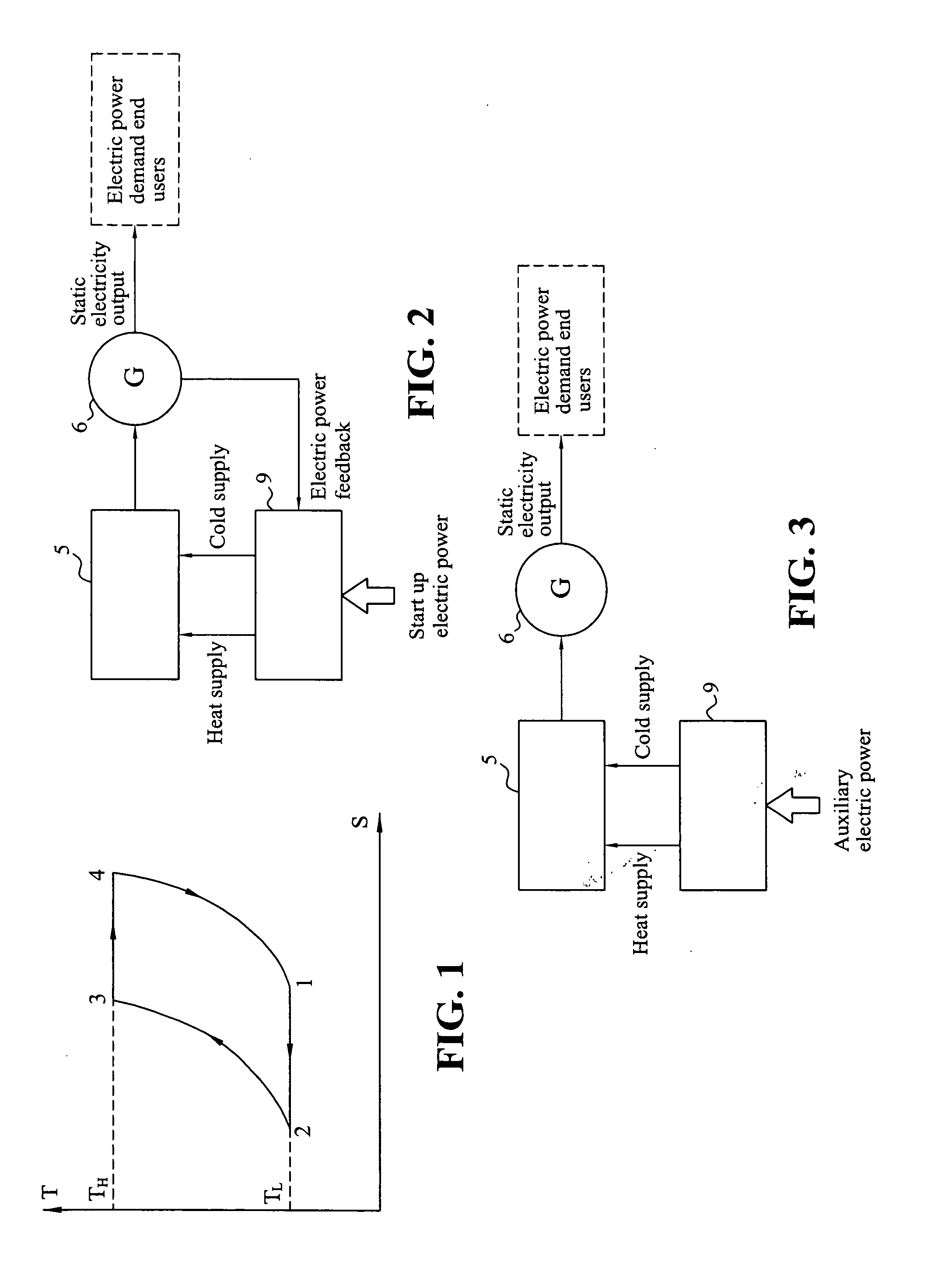
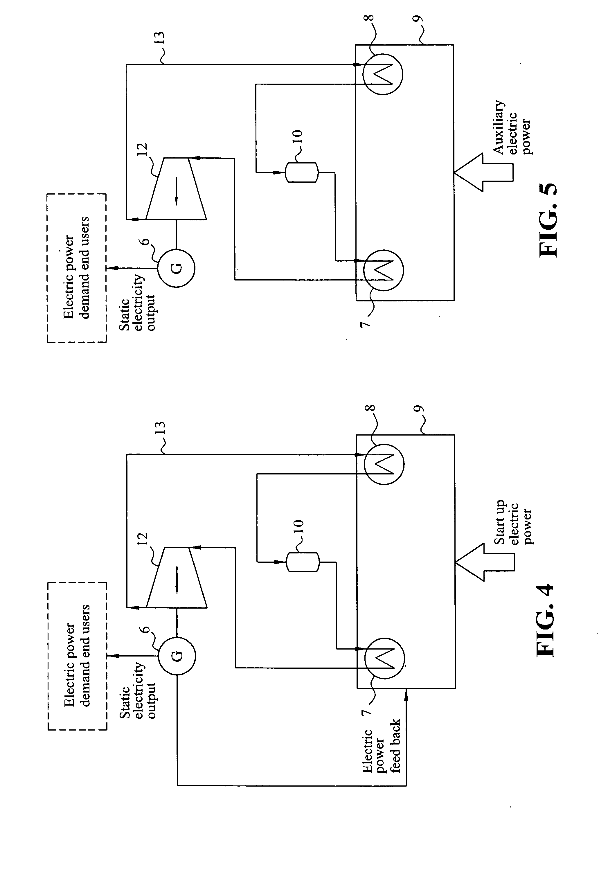
[0021]Besides, to accomplish objective of effective raising of heat source temperature and lowering of cold source temperature and then raising work efficiency of heat engine, the power generation system of the present invention utilizes heat pump to shift the heat quantity already existing in the environment. Using this method can at the same time effectively raise heat source temperature and lower cold source temperature, enabling heat engine to operate in a more favorable operating condition and most optimum utilization of energy inputted to heat pump is then performed.
[0027]Through effective raise of heat source temperature required by Stirling engine or Steam turbine by heat pump and lowering its required cold source temperature, the heat efficiency of heat engine can be effectively raised. As heat pump utilizes energy inputted to it to shift the heat quantity already existing in the environment, thereupon generating heat source and cold source required for heat engine operation, hence comparing to traditional methods of power generation by combustion of fossilized fuel, coal and natural gases etc., the power generation system of the present invention can reduce the requirements of fossilized fuel, preventing the generation of green house gases, lessening the impact of green house effect on the environment. Yet again, the power generation system of the present invention indeed contributed extremely towards environmental issues such as energy utilization and release of green house gases.

Problems solved by technology

Due to problems like temperature difference heat conduction and heat leakages between heat end and cold end of Stirling engine, so far, even though the actual heat efficiency of Stirling heat engine is too low from its theoretical value, it can still reach 20-25%.
Stirling Engine because of heat transfer problem in itself, for example heat transfer between heat end and cold end temperature difference, heat leakages during system operation, and irreversible heat regeneration process inevitably generates irreversible loss, thus causing efficiency of Stirling heat engine to be lower than heat efficiency of Carnot heat engine by 50%.
Besides, with the present rate of fossilized fuel consumption, it can be foreseen with storage quantity of fossilized fuel gradually decreasing, expenses in mining fossilized fuel and cost in purchasing fossilized fuel will become more expensive.
Power generation system using combustion of fossilized fuel will become a problem.

Method used


Image

  • Power generation system driven by heat pump
  • Power generation system driven by heat pump
  • Power generation system driven by heat pump

Examples


Embodiment Construction

[0001]The present invention relates to a type of power generation system, especially to a power generation system which utilizes heat pump driven heat engine so as to generate electrical energy, in which heat engine could be Stirling's engine or steam turbine.

BACKGROUND OF THE INVENTION

[0002]Introduction of Stirling Cycle:

[0003]Stirling Cycle is the process of isothermal heat transfer and isochoric expansion and compression, an ideal Stirling cycle possesses similar heat efficiency as that of Carnot cycle, FIG. 1 is the curve showing the relationship between temperature and entropy of Stirling cycle, in which T is Temperature, S is Entropy, 1˜4 are four work state points, which is described one by one below.

[0004]1-2 Isothermal Compression Process (Heat Quantity is Transferred from Working Fluid to Cold Source):

[0005]The displacement piston, after pushing the working fluid into the cold source, retains in the top dead center position, and the working fluid is cooled down and preserv...


PUM


Abstract

A power generation system driven by heat pump which produces a heat source by heating and a cold source by cooling for the driving of a heat engine to produce mechanical energy to drive a generator generating electrical power. Part of the power generated by the generator is fed back to the heat pump continuously, and the remaining power is provided to end users in need of electrical power. The heat engine of the power generation system can be Stirling engine or a steam turbine, wherein the heat efficiency of the Stirling engine can reach 25%, and the heat efficiency of the steam turbine can reach above 30%. The heat pump used in the power generation system can be a vapor-compression heat pump. Under operating conditions where temperature difference between the generated heat and cold sources is over 25 degree celcius, the coefficient of performance can reach above 7.

Description

DESCRIPTION OF INVENTION[0001]The present invention relates to a type of power generation system, especially to a power generation system which utilizes heat pump driven heat engine so as to generate electrical energy, in which heat engine could be Stirling's engine or steam turbine.BACKGROUND OF THE INVENTION[0002]Introduction of Stirling Cycle:[0003]Stirling Cycle is the process of isothermal heat transfer and isochoric expansion and compression, an ideal Stirling cycle possesses similar heat efficiency as that of Carnot cycle, FIG. 1 is the curve showing the relationship between temperature and entropy of Stirling cycle, in which T is Temperature, S is Entropy, 1˜4 are four work state points, which is described one by one below.[0004]1-2 Isothermal Compression Process (Heat Quantity is Transferred from Working Fluid to Cold Source):[0005]The displacement piston, after pushing the working fluid into the cold source, retains in the top dead center position, and the working fluid is...

Claims


Application Information

Patent Timeline
IPC IPC(8): F25B7/00
CPCF01K25/10F01K17/005
Inventor FANG, WEIHSIAO, CHING-YENHUANG, TUNG-SHENG
Owner FANG WEI
Learn More