Method, System, and Apparatus for Modular Central Plant

a technology of modular central plants and methods, applied in the field of methods, systems and apparatus for modular central plants, can solve the problems of increasing the cost of design, delivery and installation of a central plant, requiring substantial mechanical construction, field assembly and system integration effort, and the overall cost of building construction, so as to improve the system maintainability, reduce the system cost and assembly time, and improve the effect of scalability

Inactive Publication Date: 2008-06-05
AAF MCQUAY INC
View PDF14 Cites 34 Cited by
  • Summary
  • Abstract
  • Description
  • Claims
  • Application Information

AI Technical Summary

Benefits of technology

[0007]It is an object of the present invention to improve various problems associated with the prior art. In one implementation, the inventive system includes a chiller unit and cooling tower that are designed to be modularly assembled, transported, and interconnected, thereby decreasing system cost and assembly time, increasing system maintainability, and improving scalability for increasing capacity at a future date. The removable wall panels and roof of the present invention aid in maintainability by providing enhanced access to critical system components such as the chiller assembly. The modular nature of the present

Problems solved by technology

Also, in almost all cases, central plants are designed from scratch for each building application, and although many commercially available components are utilized, installation requires substantial mechanical construction, field assembly, and system integration effort at the building site.
As a result, the cost to design, deliver, and install a central plant is a major factor in the overall expense of building construction, and often impacts the schedule for building construction completion.
In the long run, however, selection of nonstandard components only serves to further drive up cost and delays building completion schedules.
Further, the schedule and co

Method used


Image

  • Method, System, and Apparatus for Modular Central Plant
  • Method, System, and Apparatus for Modular Central Plant
  • Method, System, and Apparatus for Modular Central Plant

Examples


Embodiment Construction

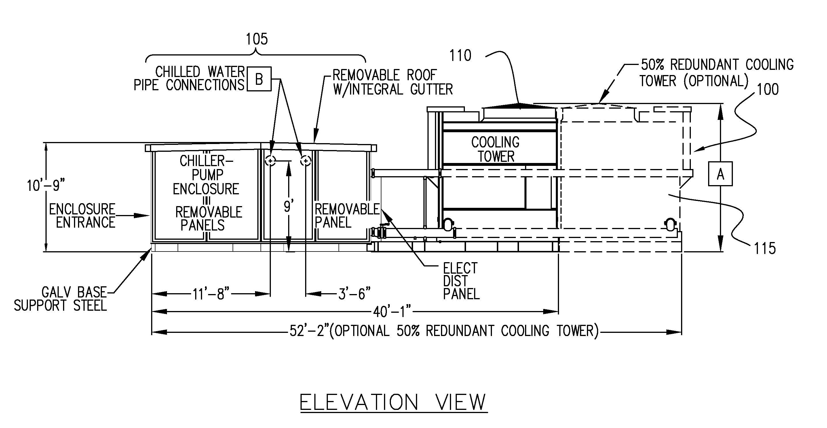
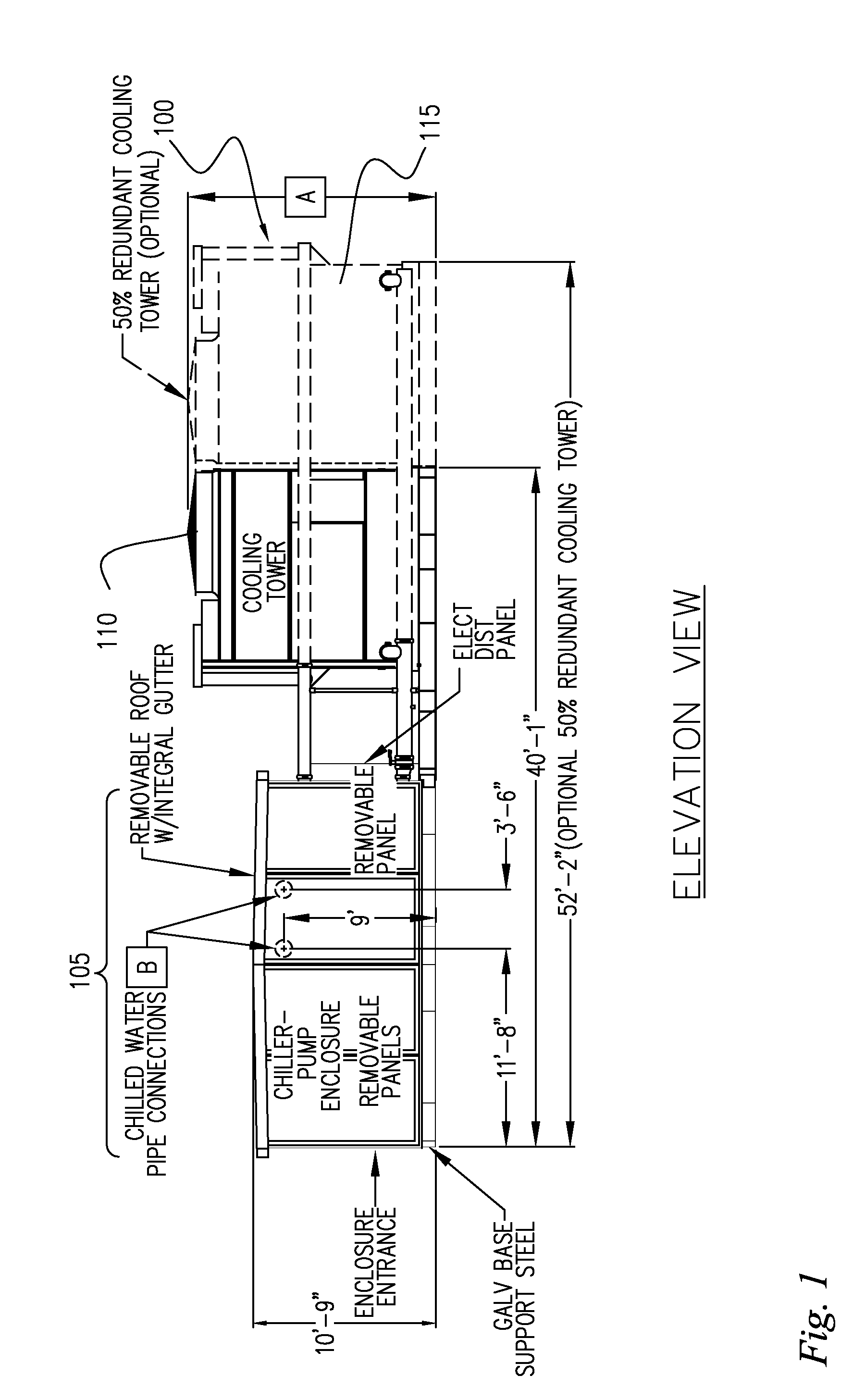
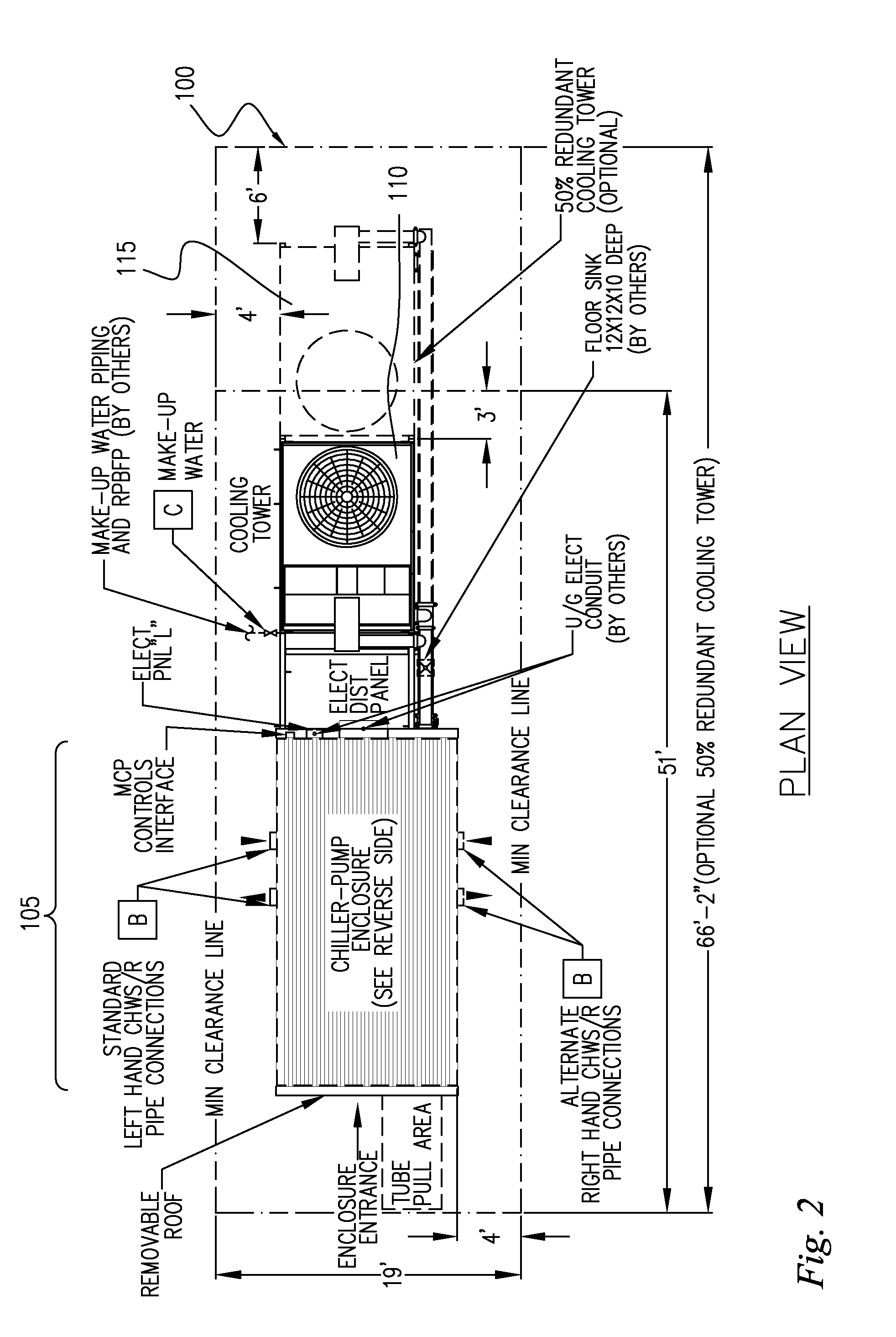
[0054]Referring to FIGS. 1 and 2, an exemplary integrated chiller-tower module 100 is shown in elevation view and plan view, respectively. In one embodiment, the integrated chiller-tower module 100 comprises a modular chiller unit 105 interconnected to a cooling tower 110. An optional additional cooling tower 115 may also be provided. FIGS. 3 and 4 show respective elevation and plan views of the chiller module 105, with removable roof panels and side panels removed to illustrate internal components and placement of piping at connection interfaces at the sides of the chiller module. Commercially available components may be utilized in the present invention to further improve cost efficiency and performance.

[0055]The modular chiller-tower units, once assembled at the jobsite and connected to building services, are fully self-contained and capable of independent operation. In one embodiment of the present invention, no additional controls or building automation systems are needed to br...


PUM


Abstract

There is provided a system and method for a modular central plant. In one implementation, the inventive system includes a chiller unit and cooling tower that are designed to be modularly assembled, transported, and interconnected, thereby decreasing system cost and assembly time, increasing system maintainability, and improving scalability for increasing capacity at a future date. The removable wall panels and roof of an embodiment of the present invention aid in maintainability by providing enhanced access to critical system components such as the chiller assembly. The modular architecture of the present invention allows for speedy delivery and installation, and with only external electrical and water connections needed, the system can become rapidly operational.

Description

CROSS REFERENCES TO RELATED APPLICATIONS[0001]This application claims the full benefit and priority of U.S. Provisional Application Ser. No. 60 / 805,213, filed on Jun. 19, 2006, the disclosure of which is fully incorporated by reference herein for all purposes.TECHNICAL FIELD[0002]The present invention relates generally to the cooling and heating equipment industry, and more specifically to methods, systems, and apparatus for modular central plants for providing heated and chilled water for building climate control.BACKGROUND[0003]To provide for efficient building climate control, particularly in larger buildings, chilled or heated water is typically furnished to building air handling systems from a central plant. These central plants typically incorporate one or more chiller / boiler units and cooling towers, and comprise sophisticated combinations of electrical and mechanical control systems, mechanical piping and fluid processing, pumps, fans, shelters, and engineered structural ele...

Claims


Application Information

Patent Timeline
IPC IPC(8): F28C1/00F25B7/00
CPCF24F3/06F24F2221/36F25D23/00F25D19/04F25B2400/21F28F2025/005
Inventor STANFIELD, MICHAEL E.LILES, KENNETH M.MULLINS, STEPHEN C.NIVER, GARY G.
Owner AAF MCQUAY INC
Why Eureka
Try Eureka