Radiation cameras

a technology of ionizing radiation and cameras, applied in the field of ionizing radiation detecting cameras, can solve the problems of not being able to give depth information and measuring the position of electrons

Inactive Publication Date: 2008-06-05
SUHAMI AVRAHAM
View PDF16 Cites 142 Cited by
  • Summary
  • Abstract
  • Description
  • Claims
  • Application Information

AI Technical Summary

Benefits of technology

[0217]If the calculated X-ray direction coincides with that of the position of the X-ray tube, the measured energy gives the specific energy out of the spectrum emitted by the X-ray source. This enables to sort the “transmission” images into groups of images, each obtained with a different X-ray energy. Thus an X-ray tube having a low Z anode such as aluminum, would emit a continuum of X-rays up to t...

Problems solved by technology

The practical obstacles are the measurement of the electron's position before the scattering and the direction of its recoil after interaction with the incoming gamm...

Method used


Image

  • Radiation cameras
  • Radiation cameras
  • Radiation cameras

Examples


Embodiment Construction

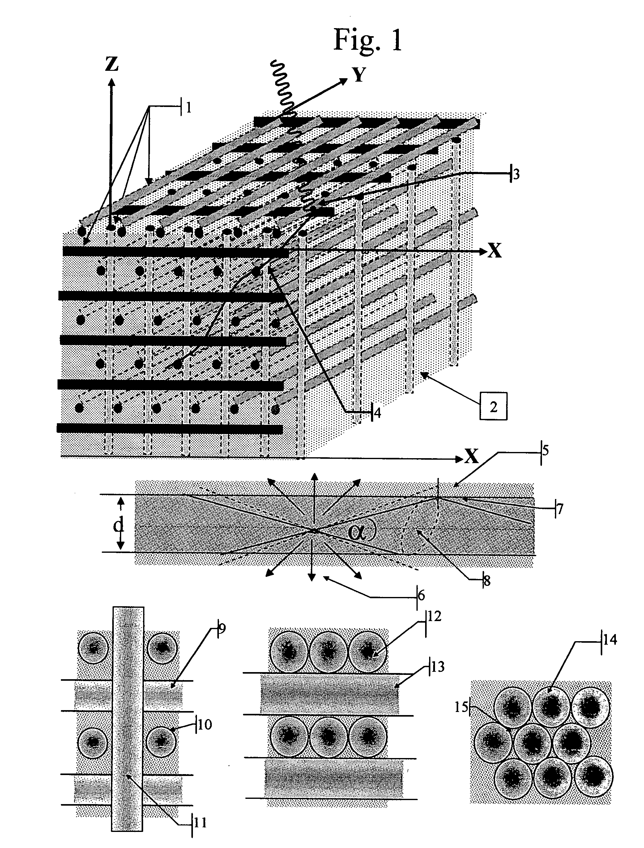
[0252]FIG. 1 illustrates a composite 3D Matrix of scintillation fibers composed of three orthogonal interlaced 3D arrays 1 of fibers separated by air or aerogel 2. A photoelectron 3 knocked-off by an incoming gamma ray would in its way traverse all three mutually orthogonal arrays and any 3 consecutive points of interaction with the Matrix would in general have coordinates (Xi,Yj), (Yj+1,Zk) and (Zk+1,Xi+1). Thus the coordinates of the Track 4 of the photoelectron along this 3 proximate points would be well defined in 3D by [(Xi+Xi+1) / 2],[(Yj+Yj+1) / 2] and [(Zk+Zk+1) / 2]. In the case that the Track crosses only two orthogonal arrays, at the proximate points (Xi,Yj) and (Yj+1,Zk), the coordinates of the Track 4 of the photoelectron along the 2 proximate points would still be defined in 3D by [(Xi), (Yj+Yj+1) / 2 and (Zk)]. In such a matrix of scintillation fibers used to detect the direction of the photo-electron Track, it is beneficial to reduce the fiber thickness and increase the sepa...


PUM


Abstract

The invention describes radiation cameras consisting of interlaced scintillation fiber arrays and a fiber readout method using pixellated photo-detector cameras. Several fabrication methods of the fiber arrays are described. The use of such Radiation Cameras in Medical Imaging systems is also described.

Description

[0001]This patent application claims the benefit of the filing of U.S. Provisional Patent application Ser. No. 60 / 815,00 filed on Jun. 21, 2006 titled “Radiation Detector” and U.S. Provisional Patent application Ser. No. 60 / 874,788 filed on Dec. 14, 2006 titled “Radiation Camera” incorporated herein by reference.FIELD OF THE INVENTION[0002]This invention relates to Ionizing Radiation Detecting CamerasRELEVANT PATENTS AND PUBLICATIONS[0003]The patents below are incorporated in this application by reference.[0004]U.S. Pat. No. 7,145,189 Photon amplification for image sensors Mouli et al.[0005]U.S. Pat. No. 7,145,149 Flexible composite radiation detector Cooke et al.[0006]U.S. Pat. No. 7,122,408 Photododes with ultra-shallow junction for high quantum efficiency CMOS image sensor and method of formation Mouli et al.[0007]U.S. Pat. No. 7,115,963 Circuitry for image sensors with avalanche photo-diodes Augusto et al.[0008]U.S. Pat. No. 7,064,406 suppression of dark current in a photo-senso...

Claims


Application Information

Patent Timeline
IPC IPC(8): G01T1/20G01T1/24C09K11/00
CPCG01T5/02
Inventor SUHAMI, AVRAHAM
Owner SUHAMI AVRAHAM
Why Eureka
Try Eureka