Inertial energy scavenger

a technology of energy scavenger and energy scavenger, which is applied in the field of energy scavenger, can solve the problems of motion of the proof mass, the configuration of the beam still too stiff to provide a robust coupling with the excitation source, and the majority of piezoelectric materials (such as pzt), so as to reduce the overall installation volume of the energy scavenger without sacrificing energy output, and improve the energy output. , the

Inactive Publication Date: 2008-06-05
LV SENSOR
View PDF11 Cites 10 Cited by
  • Summary
  • Abstract
  • Description
  • Claims
  • Application Information

AI Technical Summary

Benefits of technology

[0032]Some key advantages of the invention are robust performance at relatively low frequencies in a wide range of applications. Because piezoelectric structures are generally stiff, a force amplification mechanism allows the relatively high displacement (characteristic of low frequency applications) and low force motion of the proof mass to be converted to a high-force / low-displacement motion that couples better with the piezoelectric device. The invention reorients the direction of motion, which allows a reduction in the overall installation volume of the energy scavenger without sacrificing energy output. A single proof mass can actuate multiple piezoelectric structures that are oriented out-of-plane to each other, which can improve the energy output for a given installation volume. The transfer mechanism enables bi-stable motion of the proof mass which can improve the performance, and also contains features that provide robustness functions, where the mechanism inherently limits the maximum strain the piezoelectric device can see without resorting to limit stops that can transfer shocks to the piezoelectric material and represent manufacturing tolerance constraints. A piezoelectric surface profile in the housing supports the piezoelectric structure while under load to provide reduced peak strain levels in the piezoelectric structure. For example, constant curvature surface, onto which the piezoelectric element deflects, greatly reduces the stress concentrations, thereby reducing the possibility of fatigue cracking. This surface also provides the opportunity for the transfer mechanism to bias the piezoelectric element in compression, which reduces the risk of tension fatigue cracking. The transfer mechanism is implemented with compliant mechanisms without joints that can create energy reducing friction and unwanted component wear. Another key advantage is the transfer mechanism can be implemented with rolling structures that provide very low friction and very high out of plane stiffness.

Problems solved by technology

However, such beam configurations are still too stiff to provide a robust coupling with excitation sources that are below about 25 Hz.
At high-frequencies, the dynamics of the system under commonly occurring excitation sources usually limit the motion of the proof mass to very small displacements.
A further difficulty with piezoelectric elements used as energy scavengers is that most piezoelectric materials (such as PZT and its variants) are brittle, can fatigue with many stress cycles, particularly under tension, and can crack if overstrained or in response to shock.
These issues are more of a problem in low frequency and high displacement applications because the piezoelectric material is typically straining to a higher level on each cycle.

Method used


Image

  • Inertial energy scavenger
  • Inertial energy scavenger
  • Inertial energy scavenger

Examples


Embodiment Construction

[0037]Although the following detailed description contains many specifics for the purposes of illustration, anyone of ordinary skill in the art will readily appreciate that many variations and alterations to the following exemplary details are within the scope of the invention. Accordingly, the following preferred embodiments of the invention are set forth without any loss of generality to, and without imposing limitations upon, the claimed invention.

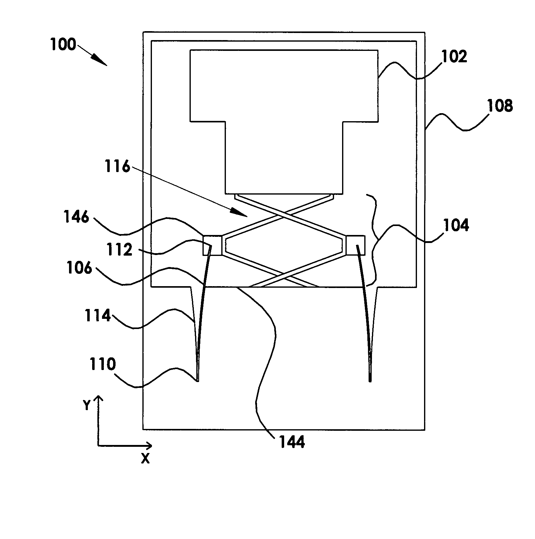
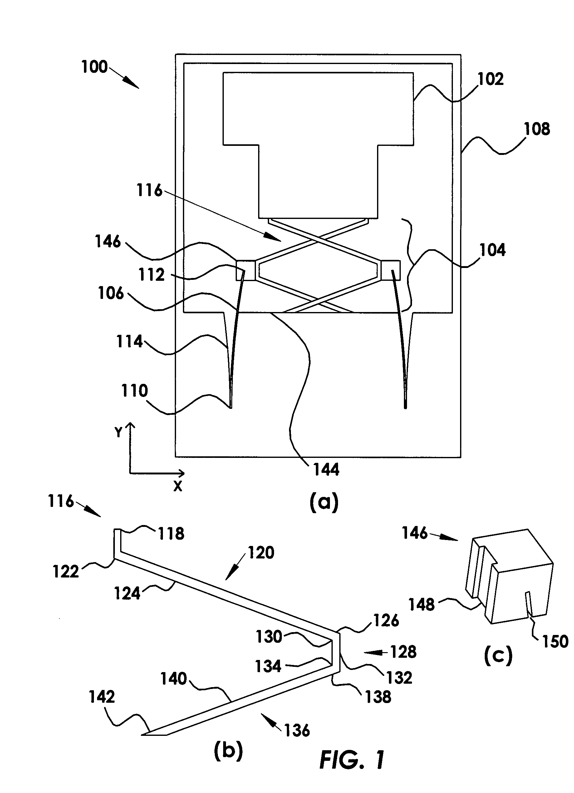
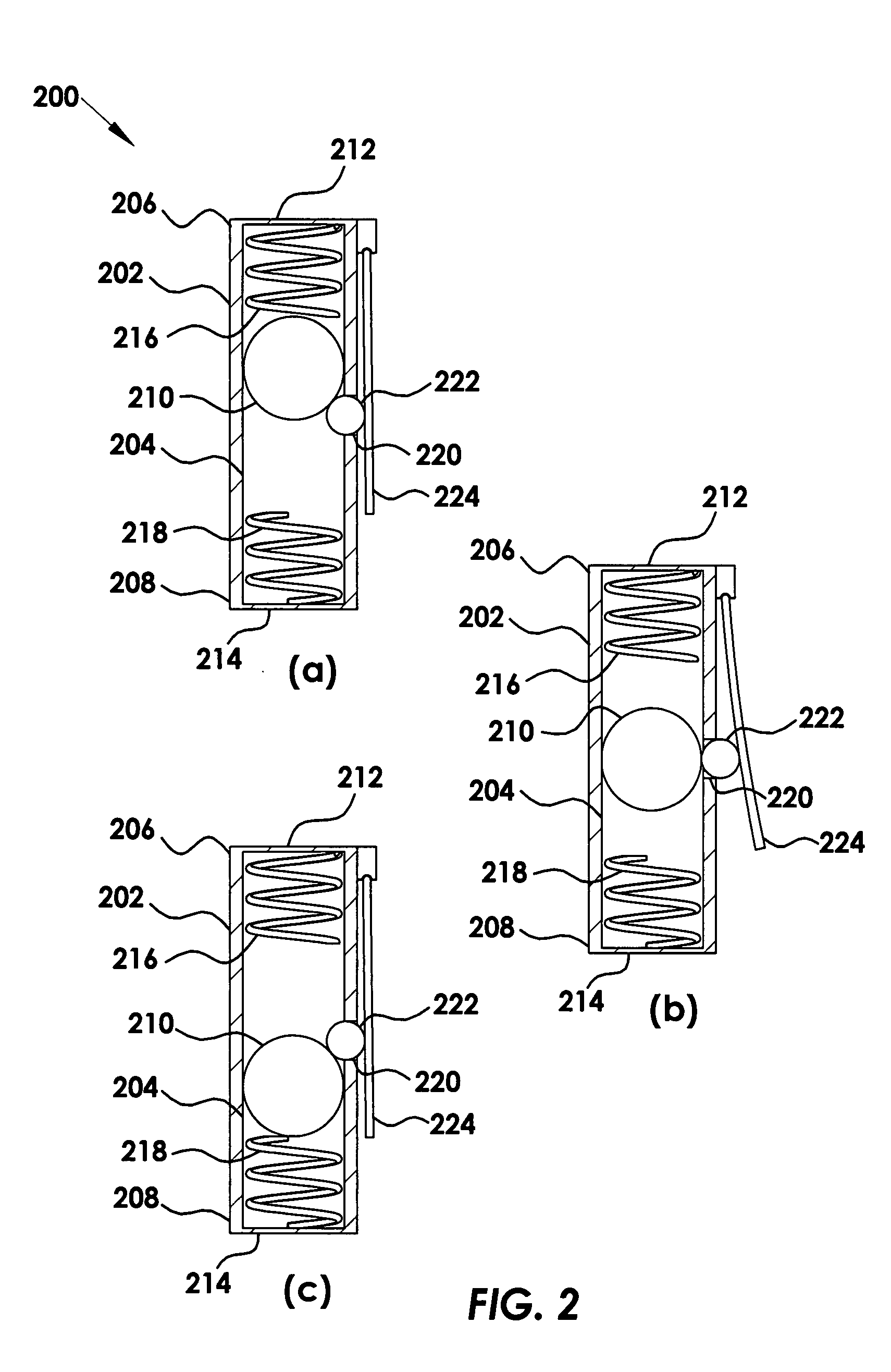
[0038]The present invention provides inertial piezoelectric energy scavengers. The inertial piezoelectric energy scavengers according to the current invention generally contain a proof mass, which actuates a piezoelectric structure. The proof mass is driven by external motion inputs such as vibrations. The invention has a mechanical transfer assembly that mechanically couples the proof mass to the piezoelectric structure. The mechanical transfer assemblies significantly improve the performance of the scavenger by providing force amplifi...


PUM


Abstract

The present invention provides an inertial energy scavenger that includes at least one piezoelectric element held by a housing, a proof mass that is movable within the housing in a direction parallel to the piezoelectric element, and a mechanical assembly disposed between the proof mass and the piezoelectric element. The mechanical assembly transfers work from the proof mass to the piezoelectric element, where the work from the proof mass is a first force along a first distance and the work to the piezoelectric element is a second force along a second distance. The first distance is greater than the second distance and the first force is smaller than the second force. Force amplification is determined by the geometry of the mechanical transfer assembly and can range anywhere from just above 1 to at least 10, where some embodiments include a bi-lever configuration, a tube-shaped configuration and a reverse actuation configuration.

Description

CROSS-REFERENCE TO RELATED APPLICATIONS[0001]This application is cross-referenced to and claims the benefit from U.S. Provisional Patent Application 60 / 817,981 filed Jun. 30, 2006, which is hereby incorporated by reference.FIELD OF THE INVENTION[0002]The present invention relates generally to energy scavenging devices. More particularly, the present invention relates force amplification in piezoelectric inertial energy scavenging.BACKGROUND[0003]Inertial energy scavengers convert ambient motion, such as vibration, into electrical energy useful for powering electronic devices such as sensors and the like. Such energy scavengers are attractive as an alternative to batteries in many applications including, but not limited to tire pressure monitoring, industrial process control, supply chain management, building thermal control, and transportation. Additionally, many long-life applications are enabled by inertial energy scavengers.[0004]Piezoelectric material converts mechanical strain ...

Claims


Application Information

Patent Timeline
Patent Type & Authority Applications(United States)
IPC IPC(8): H01L41/02
CPCH02N2/186H01L41/1136H10N30/306
Inventor ROUNDY, SHADRACH J.TOLA, JEFFRYTOLA, JEFFREY F.
Owner LV SENSOR
Why Eureka
Try Eureka