Piezoelectric ceramic composition and laminated piezoelectric element

a technology of piezoelectric elements and ceramic compositions, which is applied in the field of piezoelectric ceramic compositions and laminated piezoelectric elements, can solve the problems of insufficient displacement of actuators required to drive at high voltage, and the inability to obtain laminated piezoelectric elements at low sintering temperature, and achieve the effect of sufficient displacemen

Inactive Publication Date: 2008-06-05
TDK CORPARATION
View PDF3 Cites 13 Cited by
  • Summary
  • Abstract
  • Description
  • Claims
  • Application Information

AI Technical Summary

Benefits of technology

[0026]Here, it is to be noted that Cu forms a eutectic crystal with Pb that is a main constituent element of the piezoelectric ceramic composition, in the vicinity of 963° C. Consequently, when a laminated piezoelectric element is fabricated by using Cu as a material for the internal electrodes, the piezoelectric ceramic composition is required to be a material capable of being sintered at 950° C. or lower. Additionally, sintering of Cu in air leads to oxidation thereof, so that the sintering is required to be carried out in a low-oxygen reductive atmosphere. In this context, the piezoelectric ceramic composition according to the present invention permits obtaining a dense sintered body even by sintering in a low-oxygen reductive atmosphere.
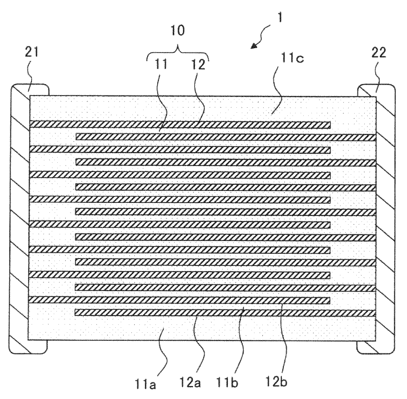
[0027]The present invention can be applied to a laminated piezoelectric element. In other words, the present invention provides a laminated piezoelectric element including a plurality of piezoelectric layers and a plurality of internal electrodes interposed between the piezoelectric layers, wherein the piezoelectric layers are formed of the above-described piezoelectric ceramic composition. In this laminated piezoelectric element, the internal electrodes can be formed of Cu. This is because the piezoelectric ceramic composition of the present invention is capable of being sintered at low temperatures and in a low-oxygen reductive atmosphere. However, the laminated piezoelectric element of the present invention is not limited to the adoption of internal electrodes formed of Cu, but permits, needless to say, the conventional use of Pt, Pd and a Ag—Pd alloy for internal electrodes, and also allows the use of low-price nickel (Ni) and other metals (inclusive of alloys) for the internal electrodes.
[0028]As described above, according to the present invention, the sintering can be carried out at low temperatures of 950° C. or lower and in a low-oxygen reductive atmosphere, and sufficient displacement can be obtained even at high voltages of 1 kV / mm or higher.

Problems solved by technology

However, according to the investigation performed thereafter by the present inventors, the piezoelectric ceramic composition of Japanese Patent Laid-Open No. 2006-193414 exhibits excellent piezoelectric properties at low applied voltages of, for example, 1 V / mm or lower, but no sufficient displacements have been obtained in products such as actuators required to be driven at high voltages.
However, for the piezoelectric ceramic composition disclosed in Japanese Patent Laid-Open No. 2006-193414, it has been found that the piezoelectric properties at a low voltage do not link with the piezoelectric properties at a high voltage.
However, the decrease of x, namely, the decrease of the relaxer component amount increases the sintering temperature for giving a sufficient density to be as high as 1100° C. or higher, and hence it is impossible to obtain laminated piezoelectric elements at low sintering temperatures.

Method used


Image

  • Piezoelectric ceramic composition and laminated piezoelectric element
  • Piezoelectric ceramic composition and laminated piezoelectric element
  • Piezoelectric ceramic composition and laminated piezoelectric element

Examples


example 1

[0113]In the present example, effects of Cu and Li were investigated by adding Cu as the first additive as Cu2O and Li as the second additive as Li2CO3 so as to give the contents shown in FIG. 6 in relation to the below-described main component. It is to be noted that the third additive was added as described below.

[0114]Main component: (Pb0.965Sr0.03)[(Zn1 / 3Nb2 / 3)0.02Ti0.46Zr0.52]O3

[0115]Third additive: Ta2O5, 0.2% by mass

[0116]Each of the piezoelectric ceramic composition samples shown in FIG. 6 was prepared as follows. First, as the raw materials for the main component, a PbO powder, a SrCO3 powder, a ZnO powder, a Nb2O5 powder, a TiO2 powder and a ZrO2 powder were prepared, and were weighed out so as to give the composition of the above-described main component. Additionally, a Cu2O powder, a Li2CO3 powder and a WO3 powder were prepared as the addition species of the first to third additives, respectively, and these powders were added to the base composition of the main compone...

example 2

[0124]Each of the samples shown in FIG. 7 was prepared in the same manner as in Example 1 except that the raw materials were prepared so as to give the value of a shown in FIG. 7 and to include the first to third additives as specified below in relation to the below-described main component. The samples thus obtained were subjected to the measurement of the piezoelectric constant d33 in the same manner as in Example 1. The results thus obtained are shown in FIG. 7.

[0125]As shown in FIG. 7, with the values of a falling within a range from 0.96 to 1.03, the improvement effect of the piezoelectric properties at high voltages can be enjoyed.

[0126]Main component: (Pba−0.03Sr0.03)[(Zn1 / 3Nb2 / 3)0.02Ti0.46Zr0.52]O3

[0127]First additive: Cu2O, 0.05% by mass

[0128]Second additive: Li2CO3, 0.025% by mass

[0129]Third additive: Ta2O5, 0.2% by mass

example 3

[0130]Each of the samples shown in FIG. 8 was prepared in the same manner as in Example 1 except that the raw materials were prepared so as to give the value of b shown in FIG. 8 and to include the first to third additives as specified below in relation to the below-described main component. The samples thus obtained were subjected to the measurement of the piezoelectric constant d33 in the same manner as in Example 1. The results thus obtained are shown in FIG. 8.

[0131]As shown in FIG. 8, with the values of b falling within a range from 0 to 0.1, the improvement effect of the piezoelectric properties at high voltages can be enjoyed.

[0132]Main component: (Pb0.995−bSrb)[(Zn1 / 3Nb2 / 3)0.02Ti0.46Zr0.52]O3

[0133]First additive: Cu2O, 0.05% by mass

[0134]Second additive: Li2CO3, 0.025% by mass

[0135]Third additive: Ta2O5, 0.2% by mass


PUM

PropertyMeasurementUnit
temperaturesaaaaaaaaaa
melting pointaaaaaaaaaa

Abstract

A piezoelectric ceramic composition includes: a composite oxide, as a main component thereof, represented by the composition formula,
Pba[(Zn1/3Nb2/3)xTiyZrz]O3,
    • wherein a, x, y and z satisfy the following
    • relations, 0.96≦a≦1.03, 0.005≦x≦0.047,
    • 0.42≦y≦0.53, 0.45≦z≦0.56, and x+y+z=1, and the following additives in the indicated percentages by mass in relation to the main component,
    • Cu as a first additive, in a content α, in terms of Cu2O, falling within a range 0<α≦0.5%;
    • at least one of Li, Co, Ni, Ga and Mg, as a second additive, in a content β, in terms of carbonate for Li, falling within a range 0<β≦0.1%, in a content δ1, in terms of oxide for Co, Ni and Ga, falling within a range 0<δ1≦0.2%, and in a content δ2, in terms of carbonate for Mg, falling within a range 0<δ2≦0.2%;
    • and at least one of Ta, Nb, W and Sb, as a third additive, in a content γ, in terms of oxide, falling within a range 0<γ≦0.6%.

Description

BACKGROUND OF THE INVENTION[0001]1. Field of the Invention[0002]The present invention relates to a piezoelectric ceramic composition suitable for the piezoelectric layers in various piezoelectric elements such as an actuator, a piezoelectric buzzer, a sound component and a sensor, and to a laminated piezoelectric element using the above-mentioned composition, and in particular, relates to a piezoelectric ceramic composition capable of being sintered at temperatures of 950° C. or lower and in a low-oxygen reductive atmosphere.[0003]2. Description of the Related Art[0004]Piezoelectric ceramic compositions to be used in such a piezoelectric element are required to be high in piezoelectric properties, in particular, large in piezoelectric strain constant. As piezoelectric ceramics capable of attaining a large piezoelectric strain constant, there have hitherto been known, for example, a ternary system (PZT) composed of lead titanate (PbTiO3; PT), lead zirconate (PbZrO3; PZ) and lead zinc...

Claims


Application Information

Patent Timeline
Patent Type & Authority Applications(United States)
IPC IPC(8): C04B35/45H01L41/187H01L41/16
CPCB32B18/00H01L41/1876C01G33/006C01P2002/52C01P2006/40C04B35/493C04B35/6264C04B2235/3203C04B2235/3206C04B2235/3208C04B2235/3213C04B2235/3215C04B2235/3224C04B2235/3251C04B2235/3258C04B2235/3275C04B2235/3279C04B2235/3281C04B2235/3284C04B2235/3286C04B2235/3291C04B2235/3294C04B2235/442C04B2235/604C04B2235/6584C04B2235/768C04B2235/79C04B2237/348C04B2237/704H01L41/083H01L41/43C01G25/006H10N30/50H10N30/8554H10N30/097
Inventor IEZUMI, KUMIKOYAMAZAKI, JUNICHISAKAMOTO, NORIMASA
Owner TDK CORPARATION
Why Eureka
Try Eureka