Microelectromechanical Electric Potential Sensor

a micro-electromechanical and electric potential technology, applied in the direction of electrostatic field measurement, instruments, measurement devices, etc., can solve the problems of affecting sensor sensitivity and accuracy, affecting the sensitivity of the sensor, and requiring frequent maintenance, so as to improve sensitivity and accuracy, the effect of reducing interferen

Inactive Publication Date: 2008-06-05
SHAFAI CYRUS +1
View PDF6 Cites 25 Cited by
  • Summary
  • Abstract
  • Description
  • Claims
  • Application Information

AI Technical Summary

Benefits of technology

[0010]In view of the foregoing disadvantages of the prior art, the present invention relates to a new and improved MEFS-type electric field/potential sensor. Using an electrothermal actuator

Problems solved by technology

For example, the rotating vane type EFM has been the instrument of choice in many applications for atmospheric science and electric power systems, but such typical EFMs are bulky, expensive, power consuming, and require frequent maintenance.
However, these conventional actuation means suffer from several distinct disadvantages.
Besides the difficulties with generating such voltages at the operat

Method used


Image

  • Microelectromechanical Electric Potential Sensor
  • Microelectromechanical Electric Potential Sensor
  • Microelectromechanical Electric Potential Sensor

Examples


Embodiment Construction

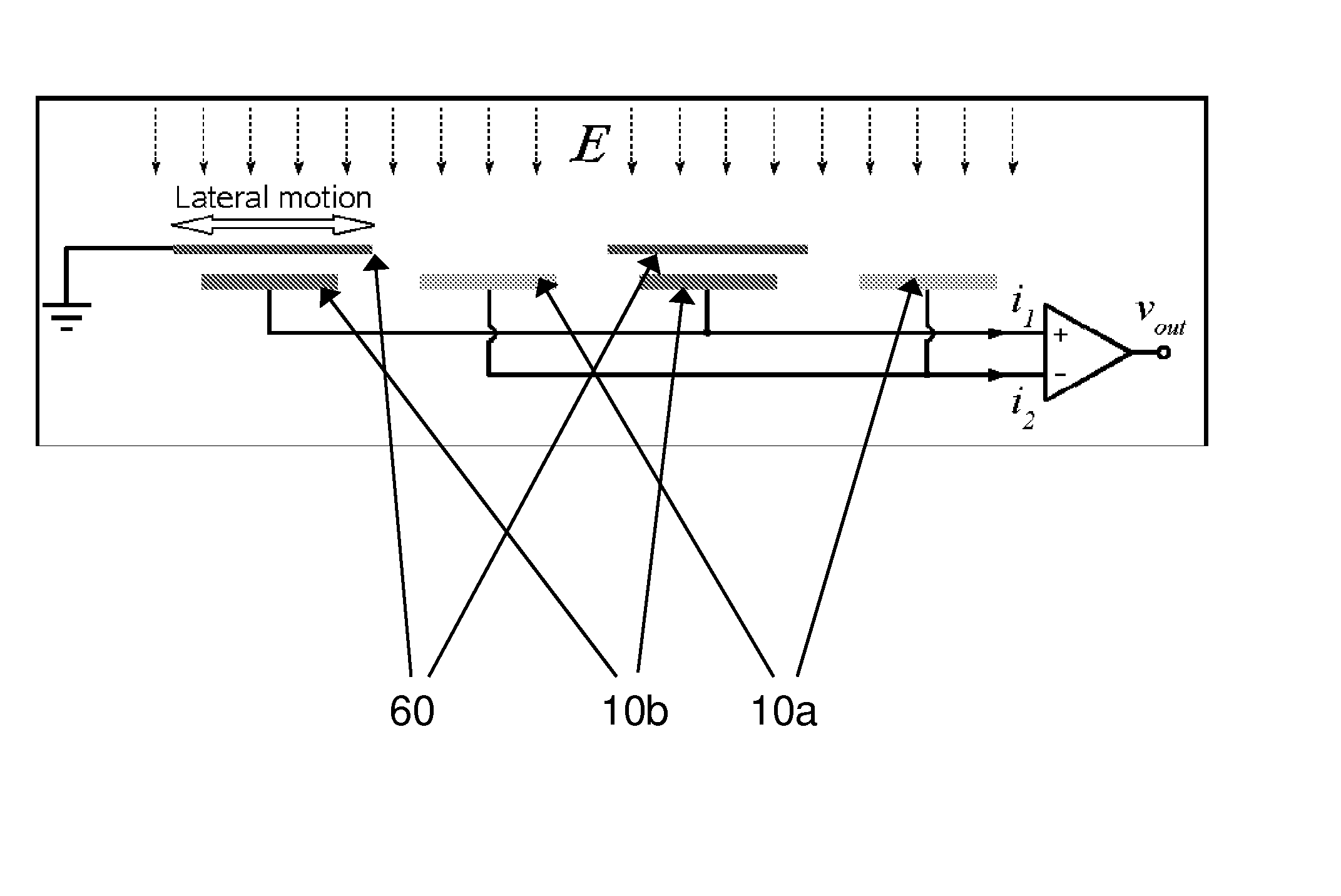
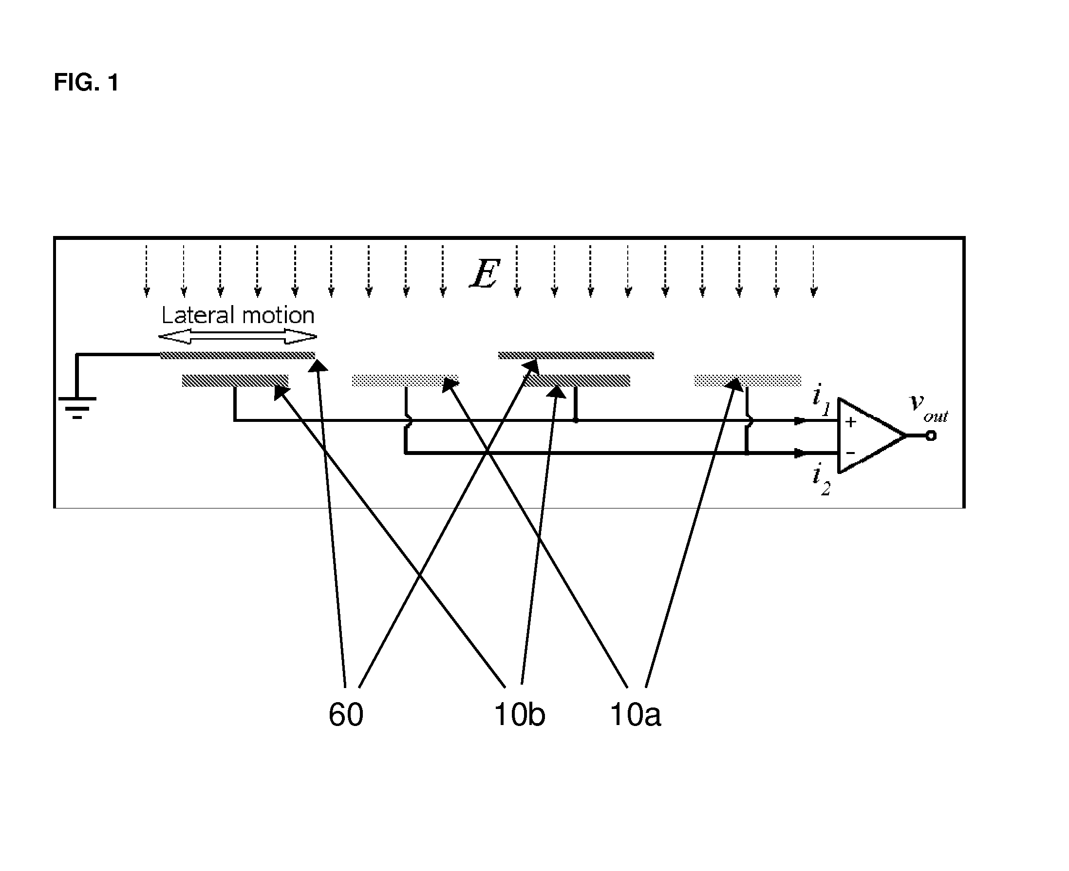
[0052]Referring to the accompanying drawings, FIG. 1 is a simple diagrammatic illustration of the basic operating principles of a microelectromechanical variable capacitive coupling electric field MEFS, illustrating the intermittent charging of the sensor electrodes 10a and 10b by the electric field as the microshutter (or shielding electrode) 60 repeatedly shields and exposes the sensor electrodes to the field. Note that the output current (signal) of electrodes 10a would be 180° asynchronous with the output current (signal) of electrodes 10b, both of which are correspondingly conveyed and manipulated downstream by conventional methods for calibration and calculation of electric field strengths.

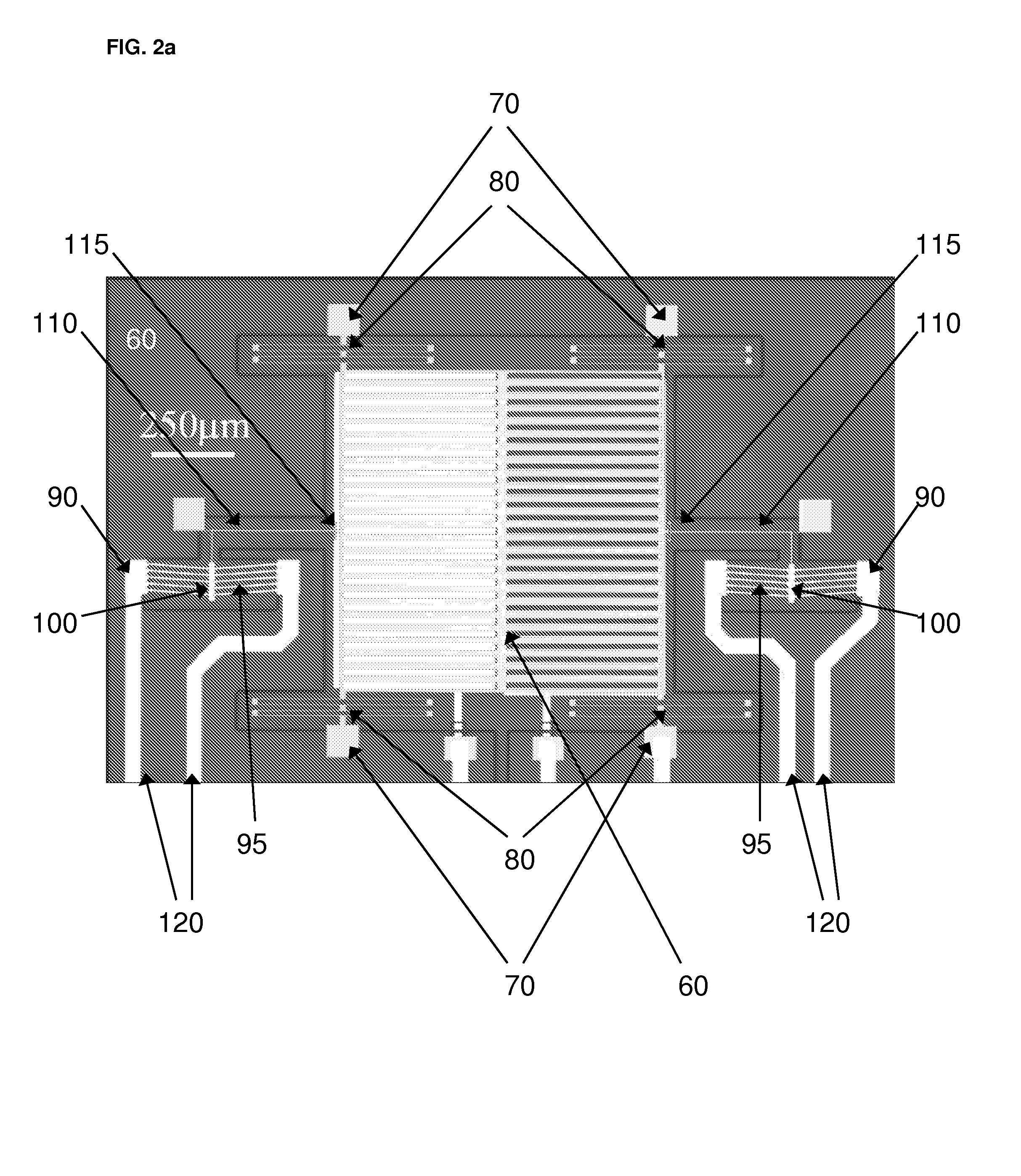
[0053]Referring to FIG. 2a, there is illustrated a microelectromechanical variable capacitive coupling electric field MEFS setup according to the present invention generally indicated by reference numeral 50.

[0054]In this particular embodiment, the MEFS 50 generally comprises two rows of sen...


PUM


Abstract

An electrical potential sensor device comprises sensor electrodes arranged to measure a voltage based on a change in electrical charge induced in the sensor electrodes by exposure to an electrical potential of a source to be measured. An electro-thermally operated mechanism, adjacent to the sensor electrodes, is movable between a first position in which only first ones of the sensor electrodes are exposed to the electrical potential of the source to be measured and other sensor electrodes are shielded from the electrical potential, and a second position in which other ones of the sensor electrodes are exposed to the electrical potential and the first ones are substantially shielded from the electrical potential. A controller combines the output from the two sets of electrodes which are alternately exposed to the electrical potential to calculate a resulting measured/sensed voltage or measured/sensed electrical potential of the device.

Description

[0001]This application claims priority to U.S. Provisional Application Ser. No. 60 / 867,897, filed Nov. 30, 2006.FIELD OF INVENTION[0002]The present invention relates in general to a novel microelectromechanical electric field / potential sensor actuated by a electrothermal mechanism, and the application thereof.BACKGROUND OF THE INVENTION[0003]It is necessary to measure the electric fields or potential in diverse applications ranging from applications in meteorology, mass spectroscopy, image formation control, biomedicine, power line monitoring, to cathodic protection monitoring for underground pipelines and alike.[0004]Electric field mills (EFM) are the most common type of electric field or potential sensors (EFS), and many different types of EFMs are used. For example, the rotating vane type EFM has been the instrument of choice in many applications for atmospheric science and electric power systems, but such typical EFMs are bulky, expensive, power consuming, and require frequent m...

Claims


Application Information

Patent Timeline
IPC IPC(8): G01R29/12
CPCG01R29/12
Inventor SHAFAI, CYRUSBAHREYNI, BEHRAAD
Owner SHAFAI CYRUS
Why Eureka
Try Eureka